Wednesday, June 12, 2013
Alarm Circuit for 5 Zone Alarm system
5 Zone Alarm Circuit
My advice is to print off a copy of the schematic then to systematically list all components of one type. Start with resistors, write down their values from the schematic and place a pencil mark against the component on the schematic. Repeat until all components have been ticked. So reading from the schematic:

There are 6 100k resistors, R1, R3, R5, R7, R9, R14.
6 1k resistors, R2, R4, R6, R8, R10, R12.
1 220k resistor R11
1 10k resistor R13. All resistors will be 1/4 watt at 5 or 10& tolerance.
5 100n capacitors, C1 to C5. These may be polyester or disc ceramic, 50V working or higher.
C6 1 100uF capacitor. This should be electrolytic have a working voltage of at least 25Volts or higher.
C7 1 1uF capacitor. Electrolytic as for C6.
3 1N4148 Diodes, D1, D2, D3 which should be readily obtainable.
1 1N4001 diode D4.
5 LEDs LED1 - LED5. Colour is not important but you may like to use the same colour for zones 2 to 5 and a different colour for zone 1, the entry, exit delay.
1 2N3904 transistor, Q1.
1 4050B CMOS IC for IC1. Note that CMOS 4050BE may also be used.
1 4072B CMOS, IC2
1 4082B CMOS IC, IC3. Note that unused inputs on ICs 2 and 3 should be connected to earth and that the power pins must be connected.
1 Relay with 2 changeover contacts. The coil needs to match the circuit, i.e. 12V coil, the relay contacts must be suitable for the load. As the load is a piezo buzzer, there will be little load current, so a miniature or sub-miniature relay may be used.
1 keyswitch
1 NO PBS (for the panic switch).
1 reed relay ( for the re-entry switch).
5 NC contact switches. These can be bought from alarm shops and fitted to doors or windows etc.
That completes the full list of components for this circuit. It is an easy matter, and can be applied to any circuit. With experience you just look at the circuit and order all the components required.
Where can I get a parts list for a particular circuit?
Answer: From the schematic, read on to find out how.
If a circuit contains less than 20 components, you dont need a separate parts list, you can obtain them straight from the schematic. If the circuit is larger than this, something may be missed, so it is handy if a parts list is available.
Prerequisites:
Before you start to write down the components, there are certain things you must know about each component. This applies to all schematics, not just the circuits on this site. This additional information is listed below :
Resistors:
Unless stated, any resistor in a circuit will be rated at 1/4 watt. This is a standard wattage and all manufacturers supply 1/4 or 1/3 watt resistors. Higher wattage resistors may be used, but are more expensive than the 1/4 watt type. Although seldom stated a resistor does have a maximum voltage rating of 1000 Volts (not by ohms law) but due to the material it is made from. If the circuit is a high voltage circuit, then special high voltage resistors must be used.
Tolerance Unless stated assume all resistors in a circuit have10% tolerance. Buying 1/3w or 1/4w resistors at 5 or 10% in bulk may save money if you are a serious hobbyist.
Capacitors:
There are many different types of capacitors, electrolytics, polyester, silver mica, tantalum bead etc. Some have different characteristics and offer advantages in particular circuits.
Working Voltage The working voltage of a capacitor MUST exceed the working voltage of a circuit. This is of greatest importance with large value electrolytics, where excess voltage may cause the chemicals in the capacitor to overheat or explode. For any given power supply I would recommend that the voltage of the capacitor be at least 3 times higher than the nominal voltage of the power supply.
Tolerance Capacitors vary widely in tolerance, electrolytics may be +/- 20% of their rated capacitance, whereas ceramic plate capacitors can be made to within 5% of their nominal value.
Capacitors in Circuits:
Unless stated on a schematic, I would recommend the using capacitors as follows:
Ceramic Disc: Decoupling logic circuits, or radio circuits
Ceramic Plate: Timing circuits or other close tolerance circuits
Electrolytic: Use in power supplies and audio circuits, or where large capacitance values are required.
Polyester Film: Decoupling circuits, RF circuits
Tantalum: Low leakage circuits, timing circuits
Inductors and Transformers:
An Inductor in its simplest form is just a coil of wire (air-spaced), however it may be wound on a core that is either iron or ferrite to increase its inductance, or wound onto a former to make a transformer. There are also high frequency transformers known as IFTs these will have a particular resonant frequency and best suited to a radio design. Inductors for a radio circuit will always be specified on the schematic. Transformers for power supplies circuits will always be specified on a schematic with the correct choice of primary and secondary ratings.
Diodes and Transistors:
The recommended first choice of transistor or diode will be stated on the circuit. If the component cannot be obtained locally then a substitute part may be used, usually chosen from a catalog or substitute handbook. If choosing an alternative part make sure the ratings match those of the original circuit.
Switches and Relays:
Switches and relays, being mechanical in nature, can be unreliable components so if you want reliability dont buy the cheaper switches. Switch and relay contacts must have voltage and current ratings greater than the load they will switch, this will be stated on the diagram. If not stated then use a switch or relay with contacts that can handle the voltage and current of the circuit.
Read More..
My advice is to print off a copy of the schematic then to systematically list all components of one type. Start with resistors, write down their values from the schematic and place a pencil mark against the component on the schematic. Repeat until all components have been ticked. So reading from the schematic:
There are 6 100k resistors, R1, R3, R5, R7, R9, R14.
6 1k resistors, R2, R4, R6, R8, R10, R12.
1 220k resistor R11
1 10k resistor R13. All resistors will be 1/4 watt at 5 or 10& tolerance.
5 100n capacitors, C1 to C5. These may be polyester or disc ceramic, 50V working or higher.
C6 1 100uF capacitor. This should be electrolytic have a working voltage of at least 25Volts or higher.
C7 1 1uF capacitor. Electrolytic as for C6.
3 1N4148 Diodes, D1, D2, D3 which should be readily obtainable.
1 1N4001 diode D4.
5 LEDs LED1 - LED5. Colour is not important but you may like to use the same colour for zones 2 to 5 and a different colour for zone 1, the entry, exit delay.
1 2N3904 transistor, Q1.
1 4050B CMOS IC for IC1. Note that CMOS 4050BE may also be used.
1 4072B CMOS, IC2
1 4082B CMOS IC, IC3. Note that unused inputs on ICs 2 and 3 should be connected to earth and that the power pins must be connected.
1 Relay with 2 changeover contacts. The coil needs to match the circuit, i.e. 12V coil, the relay contacts must be suitable for the load. As the load is a piezo buzzer, there will be little load current, so a miniature or sub-miniature relay may be used.
1 keyswitch
1 NO PBS (for the panic switch).
1 reed relay ( for the re-entry switch).
5 NC contact switches. These can be bought from alarm shops and fitted to doors or windows etc.
That completes the full list of components for this circuit. It is an easy matter, and can be applied to any circuit. With experience you just look at the circuit and order all the components required.
Where can I get a parts list for a particular circuit?
Answer: From the schematic, read on to find out how.
If a circuit contains less than 20 components, you dont need a separate parts list, you can obtain them straight from the schematic. If the circuit is larger than this, something may be missed, so it is handy if a parts list is available.
Prerequisites:
Before you start to write down the components, there are certain things you must know about each component. This applies to all schematics, not just the circuits on this site. This additional information is listed below :
Resistors:
Unless stated, any resistor in a circuit will be rated at 1/4 watt. This is a standard wattage and all manufacturers supply 1/4 or 1/3 watt resistors. Higher wattage resistors may be used, but are more expensive than the 1/4 watt type. Although seldom stated a resistor does have a maximum voltage rating of 1000 Volts (not by ohms law) but due to the material it is made from. If the circuit is a high voltage circuit, then special high voltage resistors must be used.
Tolerance Unless stated assume all resistors in a circuit have10% tolerance. Buying 1/3w or 1/4w resistors at 5 or 10% in bulk may save money if you are a serious hobbyist.
Capacitors:
There are many different types of capacitors, electrolytics, polyester, silver mica, tantalum bead etc. Some have different characteristics and offer advantages in particular circuits.
Working Voltage The working voltage of a capacitor MUST exceed the working voltage of a circuit. This is of greatest importance with large value electrolytics, where excess voltage may cause the chemicals in the capacitor to overheat or explode. For any given power supply I would recommend that the voltage of the capacitor be at least 3 times higher than the nominal voltage of the power supply.
Tolerance Capacitors vary widely in tolerance, electrolytics may be +/- 20% of their rated capacitance, whereas ceramic plate capacitors can be made to within 5% of their nominal value.
Capacitors in Circuits:
Unless stated on a schematic, I would recommend the using capacitors as follows:
Ceramic Disc: Decoupling logic circuits, or radio circuits
Ceramic Plate: Timing circuits or other close tolerance circuits
Electrolytic: Use in power supplies and audio circuits, or where large capacitance values are required.
Polyester Film: Decoupling circuits, RF circuits
Tantalum: Low leakage circuits, timing circuits
Inductors and Transformers:
An Inductor in its simplest form is just a coil of wire (air-spaced), however it may be wound on a core that is either iron or ferrite to increase its inductance, or wound onto a former to make a transformer. There are also high frequency transformers known as IFTs these will have a particular resonant frequency and best suited to a radio design. Inductors for a radio circuit will always be specified on the schematic. Transformers for power supplies circuits will always be specified on a schematic with the correct choice of primary and secondary ratings.
Diodes and Transistors:
The recommended first choice of transistor or diode will be stated on the circuit. If the component cannot be obtained locally then a substitute part may be used, usually chosen from a catalog or substitute handbook. If choosing an alternative part make sure the ratings match those of the original circuit.
Switches and Relays:
Switches and relays, being mechanical in nature, can be unreliable components so if you want reliability dont buy the cheaper switches. Switch and relay contacts must have voltage and current ratings greater than the load they will switch, this will be stated on the diagram. If not stated then use a switch or relay with contacts that can handle the voltage and current of the circuit.
Philips LED Queen Star light bulbs in Taiwan officially listed
Recently, the worlds first won the U.S. Energy Star Queen Star of Philips LED bulb is officially on sale in Taiwan. This section bulb uses 300-degree ultra-wide-angle lighting, 825 lumens, 2700K color temperature, 80% of CRI, 12W power consumption, the highest life expectancy of 25,000 hours (six hours a day, you can use 11.4 years).
Bo Jiansheng of the general manager of Philips Taiwan said that the development of green technology is the most important global issues, green sustainable development is an important core value of the Philips, Philips attaches great importance to lighting technology to enhance the quality of human life, improve energy efficiency, and practice green ecological concept, to bring comfort and quality of life of the public health.
Recently, the worlds first won the U.S. Energy Star Queen Star of Philips LED bulb is officially on sale in Taiwan. This section bulb uses 300-degree ultra-wide-angle lighting, 825 lumens, 2700K color temperature, 80% of CRI, 12W power consumption, the highest life expectancy of 25,000 hours (six hours a day, you can use 11.4 years).
Philips accounted for nearly 40 percent of the global LED light bulb market, Philips LED Queen Star has more than one million sales in the world, has made the international IEC eye certification, the German iF design awards, Time magazine boutique Medal U.S. Department of Energy L-Prize, energy-efficient lighting awards international awards.
Wednesday, June 5, 2013
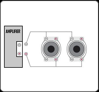
Subwoofer Wiringchina Subwoofer Wiring Supplier Factory

Basic Subwoofer Wiring For More Information Check Out Our Subwoofer.

Amp Subwoofer Wiring China Amp Subwoofer Wiring Supplier Factory.

Car Stereos Amp And Subwoofer Wiring 4 Ohm Dvc Sub Or 2ohm Dvc Sub.
Subwoofer Wiring Diagrams Sparky3489s Page By Sparky3489 Yahoo Com.

Elemental Designs Car Stereo Home Speakers Electronics.

Subwoofer Wiring Diagrams Hip Hop Universe.

Subwoofer Speaker Wiring Diagram Subwoofer Review.

Subwoofer Wiring Diagrams Four 4 Ohm Dual Voice Coil Dvc Speakers.

Discuss Ep4000 Maelstrom X Ii In The Diy Subwoofers Forum.

300w Subwoofer Power Amplifier Wiring Diagram Skema Rangkaian.
Diagram Electrical Wiring

House Wiring.

Solar Powered House Wiring.

Electrical Wiring In The Home Existing Nutone 665rsp Wiring.

Installing Home Electrical Wiring For Breakers And Fuses Inside A.

Wiring Diagram.

Diagram Electrical Wiring.

There Are Many Electrical Projects Around The House That Will Require.

Keywords House Wiring Diagram Electrical Schematic Wiring A House.

Wiring Diagram And Electrical Components Symbols For House Or Home.

Electrical Wiring In The Home Wires Are Not Hot In Electrical Outlet.
Wiring Diagram

Wiring Diagram Software Download The Best Free.
Wiring Diagram Software Provides Web Capabilities Via Development.

Free Car Wiring Diagram Software Websites Sites Google Com Mp3car.

Area Switch Unit Input Module Spectrum Intelligent Systems.

Software V0 2 1 4 Software Exe Dali Commissioning Software.

Creating Electrical Wiring Diagrams Wiring Diagram Software.

Diagramstudio Electrical Wiring Diagram Software.

Msd Ignition Wiring Diagrams And Tech Notes 1 0 License Freeware.

Wiring Diagram.
Diagram Studio Electrical Wiring Diagram Software.
Tuesday, June 4, 2013
Palmetto Networks Professional Technology Company
Wiring Diagram For Rj 45 Cat5e Cable I T On The Go Inc Computer.

Palmetto Networks A Professional Technology Company.
There Are Two Standard Cat5 And Cat6 Wiring Diagrams I Use Cat5 B.
Diagram Of Correct Color Alignment For Making Cat5e Network Cable.

Structured Wiring Retro Install 1.

How To Guide Creating Cat 5 Utp Ethernet Crossover Cable How To.

The Home Network Are The Two Wiring Patterns These Wiring Patterns Are.

Cat 5e Wiring B.

What You Should Know About Telephone And Rj45 Cat5e Wiring Codes.
Wiring Cabling Companies In Arden Fiber Optics Cat5 Cat 6 And.
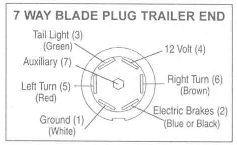
Trailer Wiring Diagram Connectors Pinoutcircuit Schematic

This Allows You To Connect Up The Wiring To Tow A Caravan Or Trailer.

Receive Requests For A Trailer Plug And Tow Bar Socket Wiring Diagram.

Pin N Type Trailer Plug Wiring Diagram Uk Trailer Parts.

Trailer Connector Wiring Diagram Which Are 7 Way Connector Wiring.

Way Trailer Wiring Diagram And Connectors Pinout Circuit Schematic.

Typical 7 Way Trailer Wiring Diagram Circuit Schematic.
Trailer Wiring Diagrams Johnson Trailer Sales Colfax Wisconsin.

Way 7 Pole Rv Travel Trailer Connector Wiring Color Code.

Trailer Wiring Diagram And Information Tridentuk Com.

Way Black Plastic Trailer Wiring Connector Circuit Schematic.
Subscribe to:
Posts (Atom)