Showing posts with label tiny. Show all posts
Showing posts with label tiny. Show all posts
Wednesday, September 24, 2014
Tiny Metronome Circuits Diagram
Tiny Metronome Circuits Diagram
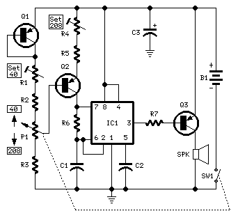
Notes:
- Q1 & Q2 provide linear frequency operation of IC1 following P1 resistance variation.
- Q3 was added in order to obtain a louder click, similar to clockwork metronomes.
- A 12V micro battery was used to obtain a higher output power and more compactness.
- Rotate P1 fully towards R2, then set R1 to obtain 40 beats per minute (compare with another metronome).
- Rotate P1 fully towards R3, then set R4 to obtain 208 beats per minute.
- Finally mark the entire scale with the usual metronome steps, as follows:
40 - 42 - 44 - 46 - 48 - 50 - 52 - 54 - 58 - 60 - 63 - 66 - 69 - 72 - 76 - 80 - 84 - 88 - 92 - 96 - 100 - 104 - 108 - 112 - 116 - 120 - 126 - 132 - 138 - 144 - 152 - 160 - 168 - 176 - 184 - 192 - 200 - 208.
Parts:
P1______100K Linear PotentiometerR1_______10K 1/2W Trimmer Cermet
R2_______10K 1/4W ResistorR3______330K 1/4W ResistorR4_______50K 1/2W Trimmer Cermet
R5______100K 1/4W ResistorR6,R7_____1K 1/4W Resistor
C1________1µF 63V Polyester CapacitorC2_______10nF 63V Polyester CapacitorC3_______47µF 25V Electrolytic CapacitorIC1_____NE555 General purpose timer IC
Q1,Q2___BC560C 45V 100mA Low noise High gain PNP Transistors
Q3_____ZTX753 100V 2A PNP TransistorSW1______SPST Switch (Ganged with P1)
SPK______8 Ohm 40mm. Loudspeaker
B1_____12V Battery (MN21, GP23A or VR22 type)

Subscribe to:
Posts (Atom)