Showing posts with label circuits. Show all posts
Showing posts with label circuits. Show all posts
Wednesday, September 24, 2014
Simple 1KHz Sine wave Generator Circuits Diagram
This simple circuit generates a good 1KHz sine wave adopting the inverted Wain bridge configuration (C1-R3 & C2-R4). It features a variable output, low distortion and low output impedance in order to obtain good overload capability. A small filament bulb ensures a stable long term output amplitude waveform.
1KHz Sine wave Generator Circuits Diagram

Notes:
- The bulb must be a low current type (12V 40-50mA or 6V 50mA) in order to obtain good long term stability and low distortion.
- Distortion @ 1V RMS output is 0.15% using a 12V 40mA bulb, raising to 0.5% with a 12V 100mA one.
- Using a bulb differing from specifications may require a change of R6 value to 220 or 150 Ohms to ensure proper circuits oscillation.
- Set R5 to read 1V RMS on an Audio Millivoltmeter connected to the output with R7 rotated fully clockwise, or to view a sinewave of 2.828V Peak-to-Peak amplitude on the oscilloscope.
- With C1, C2 = 100nF the frequency generated is 100Hz and with C1, C2 = 1nF frequency is 10KHz but R5 requires adjustment.
- High gain transistors are preferred for better performance.
Parts:
R1____________5K6 1/4W ResistorR2____________1K8 1/4W ResistorR3,R4________15K 1/4W ResistorsR5__________500R 1/2W Trimmer Cermet
R6__________330R 1/4W ResistorR7__________470R Linear PotentiometerC1,C2________10nF 63V Polyester CapacitorsC3__________100µF 25V Electrolytic CapacitorC4__________470nF 63V Polyester CapacitorQ1,Q2_______BC238 25V 100mA NPN Transistors LP1___________12V 40mA Filament Lamp Bulb (See Notes)J1__________Phono chassis Socket
SW1__________SPST Slider SwitchB1_____________9V PP3Clip for 9V PP3 Battery

Tiny Metronome Circuits Diagram
Tiny Metronome Circuits Diagram
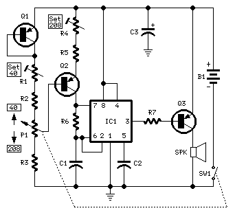
Notes:
- Q1 & Q2 provide linear frequency operation of IC1 following P1 resistance variation.
- Q3 was added in order to obtain a louder click, similar to clockwork metronomes.
- A 12V micro battery was used to obtain a higher output power and more compactness.
- Rotate P1 fully towards R2, then set R1 to obtain 40 beats per minute (compare with another metronome).
- Rotate P1 fully towards R3, then set R4 to obtain 208 beats per minute.
- Finally mark the entire scale with the usual metronome steps, as follows:
40 - 42 - 44 - 46 - 48 - 50 - 52 - 54 - 58 - 60 - 63 - 66 - 69 - 72 - 76 - 80 - 84 - 88 - 92 - 96 - 100 - 104 - 108 - 112 - 116 - 120 - 126 - 132 - 138 - 144 - 152 - 160 - 168 - 176 - 184 - 192 - 200 - 208.
Parts:
P1______100K Linear PotentiometerR1_______10K 1/2W Trimmer Cermet
R2_______10K 1/4W ResistorR3______330K 1/4W ResistorR4_______50K 1/2W Trimmer Cermet
R5______100K 1/4W ResistorR6,R7_____1K 1/4W Resistor
C1________1µF 63V Polyester CapacitorC2_______10nF 63V Polyester CapacitorC3_______47µF 25V Electrolytic CapacitorIC1_____NE555 General purpose timer IC
Q1,Q2___BC560C 45V 100mA Low noise High gain PNP Transistors
Q3_____ZTX753 100V 2A PNP TransistorSW1______SPST Switch (Ganged with P1)
SPK______8 Ohm 40mm. Loudspeaker
B1_____12V Battery (MN21, GP23A or VR22 type)
Subscribe to:
Posts (Atom)