Thursday, November 20, 2014

Audio VU Level Meter Circuit with LM324

AudioAudio VU Level Meter Circuit with LM324

The 1K resistors in the circuit are capital so that the LEDs about-face on at altered audio levels. There is no acumen why you cant change these resistors, although annihilation aloft 5K may account some of the LEDs to never about-face on. This ambit is calmly abundant with added op-amps, and is not bound to use with the LM324. Pretty abundant any op-amp will assignment as continued as you attending up the pinouts and accomplish abiding aggregate is appropriately connected.

The 33K resistor on the schematic is to accumulate the arresting ascribe to the ambit at a low level. It is absurd you will acquisition a 33K resistor, so the abutting you can get should do. The amount of this resistor may charge to be changed, so it is best you breadboard this ambit afore absolutely amalgam it on PCB. The ambit in its accepted anatomy will acquire band akin inputs from sources such as the aux out on a Hi-Fi, all admitting could be calmly adapted to acquire apostle inputs.

The audio + is affiliated to the capital absolute rail, while the audio - is acclimated for arresting input. The 50k pot can be acclimated to alter the acuteness of the circuit.

Read More..

High Frequency Waveform Generator Circuit Diagram

HighHigh Frequency Waveform Generator Circuit Diagram

High frequency waveform generator is very useful in electronic experiment and design. This circuit generate sine wave oscillation, but actually we can modify the circuit to generate triangle or square wave function.
The core of this waveform generator is MAX038. This integrated circuit chip gives complete function to build a waveform generator/function generator.

  • The circuit can be used to generate square wave, triangle, or sine wave by programming the pin inputs (A0:pin 3, A1:pin 4).
    • A0 A1 WAVEFORM
    • X 1 Sine wave
    • 0 0 Square wave
    • 1 0 Triangle wave
  • The frequency can be controlled using current. If we disconnect the 20k RIN from REF (pin 1) and connect it to a DAC, then we can control the frequency using microcontroller or digital interface. We can even control the chip using a quartz crystal (PLL) by controlling the current using a phase comparator output that compares the sync output (pin 14 of MAX038) and a reference clock from quartz crystal oscillator.

This waveform generator integrated circuit chip is very interesting since it can generate 0.1Hz to 20MHz, very wide operating frequency, as expected for every waveform generator instruments.

Read More..

Wednesday, November 19, 2014

TDA1011 4W Audio Amplifier Circuit

TDA1011 - 4W Audio Amplifier Circuit

This is 4 watts amplifier circuit diagram for implementing portable radio with TDA1011 from Philips Semiconductor.

The TDA1011 is a monolithic integrated audio amplifier in one place-9 in line (SIL) plastic container. The device is specially designed for portable radio and recording applications and offers up to 4 W at a load impedance of 4 W. The device can deliver up to 6 W 4 W to 16 V power load on the network powered applications. The maximum permissible voltage of 24 V makes this circuit very suitable for DC and AC unit, while the application supply voltage of 3.6 V low V enables applications 6.
Read More..

Battery Charger based on AVR ATMega 8535

Battery Charger in general can be interpreted as a means to recharge the battery charge. Principles of good charger circuit is capable of providing resources to perform effectively charging the battery, efficient and safe. AVR-Based Battery Charger ATMega 8535 With LCD Display This is an idea that had just emerged from the author. In AVR-Based Battery Charger design ATMega 8535 With LCD Display is using AVR microcontroller processor charger with ATMega 8535, process the data viewer charger with LCD, a safety from a hot temperature with the temperature sensor LM35 and several buttons for setting the charger. And component power charger Battery Charger Based on AVR ATMega 8535 With LCD Display is a FET.

Battery


Function-Based Battery Charger Part Series AVR ATMega 8535 With LCD Display
ATMega 8535 AVR microcontroller serves as the controlling process of the charger.
Button S1 - S5 as input data charger settings (setting the current, maximum temperature, peak voltage batteries)
LM35 Temperature Sensor function as heat sensors in the battery during charge.
LCD Display function to display data and display settings charger battery charger process measurement data.
FET serves as a power charger that will flow into the battery charging current.
Read More..

Tuesday, November 18, 2014

Automatic LED Emergency Light


Description
This is the circuit diagram of a low cost emergency light based on white LED.The white LED provide very bright light which turns on when the mains supply is not there.The circuit has an automatic charger which stops charging when the battery is fully charged.

The IC LM 317 produces a regulated 7 V for the charging of Battery.Transistor BD 140 drives the out put.Transistor BC 548 and Zener diode controls the charging of the battery.

Tips
It is always better to connect a heat sink with BD 140.Before using the circuit out put of LM317 must be set to 7V by adjusting the potentiometer.
Read More..

Ultraviolet Sensor Fire Sensor UV Tron

Ultraviolet Sensor (Fire Sensor) UV Tron is a flame sensor which is often used to detect the presence of sources of ignition under ultraviolet wave emitted by the fire. UV Sensor UV Tron can be applied with a microcontroller, such as ultraviolet UV Tron sensor is used for detecting the source of the fire on the robot in a firefighting robot contest. Tron UV ultraviolet sensor accuracy is very high against the existence of sources of fire, so it is suitable for the purpose of fire fighting robot contest that a small fire source in the form of wax.

Ultraviolet

Ultraviolet Waves:
Ultraviolet (UV is often abbreviated, of the English language: ultraviolet) are electromagnetic waves with wavelengths shorter than visible light regions, but longer than X-rays are small. UV radiation can be divided into near UV (wavelengths: 380-200 nm) and vacuum UV (200-10 nm). When considering the influence of UV radiation on human health and the environment, the wavelength range is often divided again to UVA (380-315 nm), which is also called the "wave length" or "BlackLight"; UVB (315-280 nm), also called " Medium Wave "(Medium Wave) and UVC (280-10 nm), also called" Short Wave "(Short Wave). Ultraviolet term means "beyond violet" (from the Latin ultra, "beyond"), while the word purple is the color of the shortest wavelength of light from visible light. Some animals, including birds, reptiles, and insects such as bees can see until you reach "nearly UV." Many fruits, flowers and seeds more clearly visible in the background in the UV wavelengths compared with human color vision.
UV Ultraviolet Sensor Module Tron (sensor Fire)
Read More..

Inverter 5000 Watt PWM

This inverter uses PWM (Pulse Width Modulator) with type IC SG3524. IC serves as a oscillator 50Hz, as a regulator of the desired output voltage. Input power ranging from 250W up to 5000W output and has. Following a series INVERTER 5000W with PWM (Pulse Width Modulator).
Schematic Inverter 5000W with PWM (Pulse Width Modulator)

Inverter
Layout PCB Inverter 5000W with PWM (Pulse Width Modulator)


below is the output power settings that can be issued by this inverter:
DC voltage and Transformer "T2" winding recommendation:

Winding Power Supply
12VDC 750W P: 24V "12-0-12" / S: 220V
1500W 24VDC P: 48V "24-0-24" / S: 220V
2250w 36VDC P: 72V "36-0-36" / S: 220V
3000w 48VDC P: 96V "48-0-48" / S: 220V
3750w 60VDC P: 120V "60-0-60" / S: 220V
4500w 72VDC P: 144V "72-0-72" / S: 220V
5250w 84VDC P: 168V "84-0-84" / S: 220V

Transformer used is the transformer CT
R1 serves to regulate the voltage to 220v inverter
R2 serves to regulate the inverter output frequency of 50 or 60 Hz (as appropriate)
Read More..

Monday, November 17, 2014

14W Class A Amplifier Circuit with 2N3055

14W Class A Amplifier Circuit with 2N3055

This class A amplifier circuit requires a preamp as it hasnt got much gain. Requires large heat sinks and a large transformer and a source of great power and wiring carefully, but the end is very simple and sounds great. The zener diode disclaims any wave from the power supply, but still just want a wave of 10mV max. The ripples reaching the entrance is amplified, so the zener get rid of that, but there is still dominated him to reach the power stage.

Many early amplifiers operated in Class A, but as 10W power output rose above the problems of heat dissipation and design of the power supply caused most manufacturers to turn to the simplest, arrangements more efficient class B and put up with the consequent decrease in the perceived quality of output. Why Class? Because, when biased in class A, the transistors are always on, always ready to respond instantly to an input signal. Class B and Class AB output stage requires a microsecond or more on. The kind of a cleaner operation allows operation under high voltage swing that occurs when the transient audio signal feed difficult loads. Your amplifier is basically simple, as shown in the block diagram.
Read More..

Improving Performance Bass Guitar

1. Replace strings: strings are the source of the sound of a bass. If bad strings, of course difficult to get a good sound. How good / expensive any bass, if strings are mendem ("dead") would sound so bad

2. Know your bass character of us, whether inclined treble, middle, or ngebass (low). From here our reference point. If soundnya not in accordance with our desires, try to correction with tone control / equalizer.

3. There are so many factors affecting the bass sounds, ranging from strings, pickups, body wood, neck & fingerboard.
Try to identify the character masing2, eg the influence of wood types, pickup types, etc..
From there we can determine which one should be modified.

Chain audio a bass sound as follows
Strings-> pickup-> Preamp / Tone Control-> Connection Cable-> Amplifier
Well, just select which one would aja in mod.

Actually the material (wood) body / neck / fingerboard also influence:

String-> Body/Neck/Fingerboard-> Pickup-> Preamp / Tone Control-> Connection Cable-> Amplifier (+ Speaker)

Only if you replace the body just wrote instead of bass.
So, if you can choose a distinguished bass wood is good, Ntar if you want to be upgraded more easily.
If wood is not good (Agathis), although the results are less than the maximum upgrade.
Read More..

Sunday, November 16, 2014

Triac Light Switch circuit

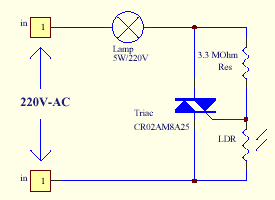
The series of light switches this time slightly different from the stress of work. The series of light switches can work directly on the AC power network. Light switches are using the main component of TRIAC and LDR. The circuit is very simple and the components were sold in the market. If you want a light reception sensitivity of this circuit can be arranged then the 3.3 MOhm resistor can be replaced with a variable resistor. For more details can be seen from the following series of images.

Triac  Light Switch circuit
Triac


Triac  Light Switch circuit series is priciple work as dimers, but dimers of control carried out by the reception of light around the LDR. The lower the intensity cayaha received LDR then semkin bright lights. For installation LDR need to be considered so as not exposed to light from the lamp directly.
Read More..

Saturday, November 15, 2014

Introduction to Cellular Communications 2

3. Cellular System Architecture

Increases in demand and the poor quality of existing service led mobile service providers to research ways to improve the quality of service and to support more users in their systems. Because the amount of frequency spectrum available for mobile cellular use was limited, efficient use of the required frequencies was needed for mobile cellular coverage. In modern cellular telephony, rural and urban regions are divided into areas according to specific provisioning guidelines. Deployment parameters, such as amount of cell-splitting and cell sizes, are determined by engineers experienced in cellular system architecture.
Provisioning for each region is planned according to an engineering plan that includes cells, clusters, frequency reuse, and handovers.

Cells

A cell is the basic geographic unit of a cellular system. The term cellular comes from the honeycomb shape of the areas into which a coverage region is divided. Cells are base stations transmitting over small geographic areas that are represented as hexagons. Each cell size varies depending on the landscape. Because of constraints imposed by natural terrain and man-made structures, the true shape of cells is not a perfect hexagon.

Clusters

A cluster is a group of cells. No channels are reused within a cluster. Figure 4 illustrates a seven-cell cluster.

A cluster is a group of cells

Frequency Reuse

Because only a small number of radio channel frequencies were available for mobile systems, engineers had to find a way to reuse radio channels to carry more than one conversation at a time. The solution the industry adopted was called frequency planning or frequency reuse. Frequency reuse was implemented by restructuring the mobile telephone system architecture into the cellular concept.
The concept of frequency reuse is based on assigning to each cell a group of radio channels used within a small geographic area. Cells are assigned a group of channels that is completely different from neighboring cells. The coverage area of cells is called the footprint. This footprint is limited by a boundary so that the same group of channels can be used in different cells that are far enough away from each other so that their frequencies do not interfere. 
Frequency Reuse

Cells with the same number have the same set of frequencies. Here, because the number of available frequencies is 7, the frequency reuse factor is 1/7. That is, each cell is using 1/7 of available cellular channels.

Cell Splitting

Unfortunately, economic considerations made the concept of creating full systems with many small areas impractical. To overcome this difficulty, system operators developed the idea of cell splitting. As a service area becomes full of users, this approach is used to split a single area into smaller ones. In this way, urban centers can be split into as many areas as necessary to provide acceptable service levels in heavy-traffic regions, while larger, less expensive cells can be used to cover remote rural regions.

Cell Splitting

Handoff

The final obstacle in the development of the cellular network involved the problem created when a mobile subscriber traveled from one cell to another during a call. As adjacent areas do not use the same radio channels, a call must either be dropped or transferred from one radio channel to another when a user crosses the line between adjacent cells. Because dropping the call is unacceptable, the process of handoff was created. Handoff occurs when the mobile telephone network automatically transfers a call from radio channel to radio channel as a mobile crosses adjacent cells.
                                                                             
Cell Phone Handoff


During a call, two parties are on one voice channel. When the mobile unit moves out of the coverage area of a given cell site, the reception becomes weak. At this point, the cell site in use requests a handoff. The system switches the call to a stronger-frequency channel in a new site without interrupting the call or alerting the user. The call continues as long as the user is talking, and the user does not notice the handoff at all.
Read More..

Friday, November 14, 2014

PHOTO SWITCH CIRCUIT USING NE 555

This is a simple photo switch suitable for home and industrial purpose. The circuit switches on a relay when the light intensity falling on the sensor crosses the set limit.The circuit is based on a NE 555 and two transistors for driving the relay. The resistor R1 is adjusted such a way that under normal condition the voltage across the LDR is less than 1/3 the supply voltage. In this condition output of IC is high .This makes transistor Q1 on. Transistor Q2′s base is connected to collector of Q1. So Q2 will be off keeping the relay de energized. When light falls the voltage across LDR rises above 2/3 Vcc. This makes the output of IC go high making the relay to energized. The result we get a relay that operates according to the intensity of light falling on the LDR.

Circuit Diagram and Parts List


Important Points

  • Assemble the circuit on a good quality PCB or common board.
  • To setup the circuit switch on power supply, connect a multimeter across LDR and adjust R1 so that voltage across LDR is just below 1/3 supply voltage. Ensure that relay is off in this condition. If not reduce voltage across LDR further more by adjusting R1 to make relay off.
  • Now cover the top of LDR using a black paper and see the relay gets activated. If not, make further adjustments with R1. Nothing to care after some trial and error you will get the correct set piont of R1 where the circuit works. This circuit  is nothing great, but some simple basics. I have tested this and got good results.
  • If there is some chattering in the relay, that may be because off the difference between the turning on and turning off voltages. This can be avoided by connecting a resistor whose value is equal to 1/2 the resistance of LDR at illuminated condition.
Read More..

Thursday, November 13, 2014

NJM2582 bassed 4 channel video amplifier electronic project circuit with explanation

 njm2582 bassed 4-channel video amplifier electronic project circuit with explanation

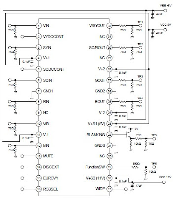
A very simple 4 channel video amplifier electronic circuit project can be designed using NJM2582 ic suitable for video applications with SCART connector . Design of the circuit is very simple and require few external electronic parts .

Some features of the NJM2582 are : Operating Voltage ±5V, +5V, +11V ; 6input 4output , 2input 1output Video SW , Internal LPF , 6dB Amplifier , Internal 75Ω Driver Circuit , DC output for SCART (FUNCTION SW, BLANKING) .

Read More..

DC motor 12V speed controller circuit with explanation

 dc motor 12v speed controller circuit with explanation

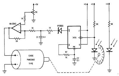
A very simple encoder circuit for a dc motor can be constructed using this circuit diagram . As you can see in the circuit diagram , the system shown consists of the HA-2542, a small 12-Vdc motor, and a position encoder. During operation, the encoder causes a series of constant-width" pulses to charge CI. The integrated pulses develop a reference voltage, which is proporţional to motor speed and is applied to the inverting input of HA-2542, The noninverting input is held at a constant voltage, which represents the desired motor speed. A difference between these two inputs will send a corrected drive signal to the motor, which completes the speed control system loop.

As you can see the circuit requires few external components , but because of the encoder wheel it has a limitations of use .If you put a pulley under the encoder wheel you can command the speed of other device , by connecting the (motor and other device ) using a belt

Read More..

Wednesday, November 12, 2014

FM Power Amplifier 250mW

This project is a simple 2-transistor VHF power amplifier, with about 16dB gain, and requires no tuning or alignment procedures. Wideband techniques have been used in the design and the circuit is equipped with a "lowpass" filter to ensure good output spectral purity. The project has been designed for assembly on a single-sided printed circuit board. The circuit is specifically designed to amplify the output of 7mW to 10mW WBFM transmitters (wide band) to a final level of 250mW to 300mW, after the filter.


Circuit Description
The first stage (Q1) operates in Class-A. Although Class-A is the least efficient mode, it does offer more RF gain than other clases of bias, and Q1 is a low-level stage, when compared to the higher power Q2 stage. The output of this stage is around 70mW of RF power. The stage is
untuned so that it gives a very broadband characteristic. The transistor is biased by means of R5, R6 and L6, and the residual (standing) DC current is set by R4. The input signal is coupled by C9 to the Base of the transistor. Q2 is operated in Class-AB which leads to greater efficiency, but the RF gain is only about 8dB, but it amplifies the output of Q1 to typically 250mW. Q2 is
biased by means of R3, R2 and L4. The input signal from Q1 is coupled to the Base of Q2 via C7.
The voltage regulator Q3 (78L08) is used to regulate the supply voltage to Q1 and the bias votages to both Q1 and Q2 so that the output RF power is relatively constant, even with large variations of supply voltage. Q3 also removes supply ripple as well as providing power for an
FM transmitter like Kit 3018 wireless microphone with the required DC 8v power.

The output of the amplifier is filtered with a low-pass filter to reduce the output spurious and harmonic content. The output filter consists of C3, C4, L1 and L2.

COMPONENTS
Resistors 5%, 1/4W, carbon:
10R R1 brown black black
22R R7 red red black
47R R3 yellow orange black
120R R4 brown red brown
470R R2 yellow violet brown
2K2 R5 red red red
4K7 R6 yellow violet red
2N2369 Q1
2N4427 Q2 1
Ceramic caps
33p C3
47p C4
1n C5 C6 C7 C8 C9
10n C1 C11
Ecaps:
220u/16V C2
10u/25V C10
78L08 Q3
RFC L4 L5 L6
Ferrite L3
3 turn coil L2
5 turn coil L1
2 pole terminal block
HS106 heatsink ( 
Read More..

LM4906 Boomer Audio Power Amplifier circuit and epxlanation

The well-known LM386 is an excellent choice for many designs requiring a small audio power amplifier (1-watt) in a single chip. However, the LM386 requires quite a few external parts including some electrolytic capacitors, which unfortunately add volume and cost to the circuit. National Semiconductor recently introduced its Boomer® audio integrated circuits which were designed specifically to provide high quality audio while requiring a minimum amount of external components (in surface mount packaging only). The LM4906 is capable of delivering 1 watt of continuous average power to an 8-ohm load with less than 1% distortion (THD+N) from a +5 V power supply. The chip happily works with an external PSRR (Power Supply Rejection Ratio) bypass capacitor of just 1 µF minimum.
In addition, no output coupling capacitors or bootstrap capacitors are required which makes the LM4906 ideally suited for cellphone and other low voltage portable applications. The LM4906 features a low-power consumption shutdown mode (the part is enabled by pulling the SD pin high). Additionally, an internal thermal shutdown protection mechanism is provided. The LM4906 also has an internal selectable gain of either 6 dB or 12 dB. A bridge amplifier design has a few distinct advantages over the single-ended configuration, as it provides differential drive to the load, thus doubling output swing for a specified supply voltage. Four times the output power is possible as compared to a single-ended amplifier under the same conditions (particularly when considering the low supply voltage of 5 to 6 volts).Circuit diagram:
Boomer Audio Power Amplifier Circuit Diagram

When pushed for output power, the small SMD case has to be assisted in keeping a cool head. By adding copper foil, the thermal resistance of the application can be reduced from the free air value, resulting in higher PDMAX values without thermal shutdown protection circuitry being activated. Additional copper foil can be added to any of the leads connected to the LM4906. It is especially effective when connected to VDD, GND, and the output pins. A bridge configuration, such as the one used in LM4906, also creates a second advantage over single-ended amplifiers. Since the differential outputs, Vo1 and Vo2, are biased at half-supply, no net DC voltage exists across the load.

This eliminates the need for an output coupling capacitor which is required in a single supply, single-ended amplifier configuration. Large input capacitors are both expensive and space hungry for portable designs. Clearly, a certain sized capacitor is needed to couple in low frequencies without severe attenuation. But in many cases the speakers used in portable systems, whether internal or external, have little ability to reproduce signals below 100 Hz to 150 Hz. Thus, using a large input capacitor may not increase actual system performance. Also, by minimizing the capacitor size based on necessary low frequency response, turn-on pops can be minimized.
Read More..

Tuesday, November 11, 2014

ICL7106 and ICL7106 based digital voltmeter circuit

ICL7106
ICL7106
ICL7106
The ICL7106 and ICL7107 are high performance, low power, 31/2 digit A/D converters including seven segment decoders , display drivers, a reference, and a clock.
The ICL7106 is designed to interface with a liquid crystal display (LCD) and includes a multiplexed backplane drive and the ICL7107 will directly drive an instrument size light emitting diode (LED) display.
Main features of ICL7106 and ICL7107 are : True Polarity at Zero for Precise Null Detection , 1pA Typical Input Current ,True Differential Input and Reference, Direct Display Drive - LCD ICL7106- LED lCL710 , Low Noise - Less Than 15μVP-P , On Chip Clock and Reference , Low Power Dissipation - Typically Less Than 10mW.
Using the ICL7106 and ICL7107 electronic schematic presented in this sheet you can make a simple and very useful digital voltmeter , using few external components .
As you can see in this schematic circuits you can make a digital voltmeter with a LED display or using a liquid crystal display .
Read More..

Sunday, November 9, 2014

Build LED Light Pen Schematic

Physicians and repair engineers often use small light pens for visual examination purposes. Rugged and expensive as these pens may be, their weak point is the bulb, which is a ‘serviceable’ part. In practice, that nearly always equates to ‘expensive’ and / or ‘impossible to find’ when you need one.

LEDs have a much longer life than bulbs and the latest ultra bright white ones also offer higher energy-to-light conversion efficiency. On the down side, LEDs require a small electronic helper circuit called ‘constant-current source’ to get the most out of them.
 
LED Light Pen Circuit Diagram
LED-Light-Pen-Circuit-Diagram

Here, T1 and R1 switch on the LED. R2 acts as a current sensor with T2 shunting off (most of) T1’s base bias current when the voltage developed across R2 exceeds about 0.65 V. The constant current through the white LED is calculated from

R2 = 0.65 / ILED
With some skill the complete circuit can be built such that its size is equal to an AA battery. The four button cells take the place of the other AA battery that used to be inside the light pen.
Read More..

Saturday, November 8, 2014

Battery Switch With Low Dropout Regulator

In the form of the LT1579 Linear Technology (www.linear-tech.com) has produced a practical battery switch with an integrated low-dropout regulator. In contrast to previous devices no diodes are required. The circuit is available in a 3.3 V version (LT1579CS8-3.3) and in a 5 V version (LT1579CS8-5), both in SO8 SMD packages. There is also an adjustable version and versions in an SO16 package which offer a greater range of control and drive signals. The main battery, whose terminal voltage must be at least 0.4 V higher than the desired output voltage, is connected to pin IN1. The backup battery is connected to pin IN2. The regulated output OUT can deliver a current of up to 300 mA. The LDO regulator part of the IC includes a pass transistor for the main input voltage IN1 and another for the backup battery on IN2.

Battery_Switch_With_LDO_Regulator_Circuit_Diagramw


The IC will switch over to the backup battery when it detects that the pass transistor for the main voltage input is in danger of no longer being able to maintain the required output voltage. The device then smoothly switches over to the backup battery. The open-drain status output BACKUP goes low to indicate when this has occurred. When neither battery is able to maintain the output voltage at the desired level the open-drain output DROPOUT goes low. The LT1579 can operate with input voltages of up to +20 V from the batteries. The regulator output OUT is short-circuit proof. The shutdown input switches off the output; if this feature is not required, the input can simply be left open.
Read More..

Simple Pulse train to sinusoid converter

The circuit letsyou convert a serial pulse stream or sinusoidal input to a sinusoidal output at 1/32 the frequency. By varying the frequency of Vrn, you can achieve an output range ofl07:1-from about 100 kH2 to less than 0.01 H2. The output resembles that of a 5-bit d/a converter operating on paralleLdigital data. Counter IC1 generates binary codes that repeatedly scan the range from 00000 to 11111. The output amplifier adds the corresponding XOR gate outputs, Vvv or ground, weighted by the values of input resistors R1 through R4.


The 16 counter codes 00000 to 01111, for instance, pass unchanged to the XOR gate outputs, and cause Vom to step through the half-sinusoidal cycle for maximum amplitude to minimum amplitude. Counter output Q4 becomes high for the next 16 codes, causing the XOR gates to invert the QO through Q3 outputs. As a result, VouT steps through the remaining half cycle from minimum to maximum amplitude. The counter then rolls over and initiates the next cycle. You can change the R1 through R4 values to obtain other VouT waveforms. VDv should be at least 12 V to assure maximum-frequency operation from IC1 to IC2.
Read More..

Friday, November 7, 2014

Telephone Headgear Circuit Diagram


Acompact, inexpensive and low component count telecom head- set can be constructed using two readily available transistors and a few other electronic components. This circuit is very useful for hands-free operation of EPABX and pager communication. Since the circuit draws very little current, it is ideal for parallel operation with electronic telephone set. Working of the circuit is simple and straightforward. Resistor R1 and an ordinary neon glow- lamp forms a complete visual ringer circuit.

This simple arrangement does not require a DC blocking capacitor because, under idle conditions, the telephone line voltage is insufficient to ionise the neon gas and thus the lamp does not light. Only when the ring signal is being received, it flashes at the ringing rate to indicate an incoming call. The bridge rectifier using diodes D1 through D4 acts as a polarity guard which protects the electronic circuit from any changes in the telephone line polarity.

Zener diode D5 at the output of this bridge rectifier is used for additional circuit protection. Section comprising transistor T1, resistors R2, R3 and zener diode D6 forms a constant voltage regulator that provides a low voltage output of about 5 volts. Dial tone and speech signals from exchange are coupled to the receiving sound amplifier stage built around transistors T2 and related parts, i.e. resistors R7, R6 and capacitor C5. Amplified signals from collector of transistor T2 are connected to dynamic receiver RT-200 (used as earpiece) via capacitor C7. A condenser microphone, connected as shown in the circuit, is used as transmitter. Audio signals developed across the microphone are coupled to the base of transistor T1 via capacitor C3. Resistor R4 determines the DC bias required for the microphone. After amplification by transistor T1, the audio signals are coupled to the telephone lines via the diode bridge. The whole circuit can be wired on a very small PCB and housed in a medium size headphone, as shown in the illustration. For better results at low line currents, value of resistor R2 may be reduced after testing
Read More..

Heat Detector Alarm using UM3561

A very simple heat detector alarm electronic project can be designed using the UM3561 sound generator circuit and some other common electronic parts . This heat detector electronic circuit project uses a complementary pair comprising npn and pnp transistor to detect heat Collector of T1 transistor is connected to the base of the T2 transistor , while the collector of T2 transistor is connected to RL1 relay T3 and T4 transistors connected in darlington configuration are used to amplify the audio signal from the UM3561 ic.

When the temperature close to the T1 transistor is hot , the resistance to the emitter –collector goes low and it starts conducting . In same time T2 transistor conducts , because its base is connected to the collector of T1 transistor and the RL1 relay energized and switches on the siren which produce a fire engine alarm sound. This electronic circuit project must be powered from a 6 volts DC power supply , but the UM3561 IC is powered using a 3 volt zener diode , because the alarm sound require a 3 volts dc power supply. The relay used in this project must be a 6 volt / 100 ohms relay and the speaker must have a 8 ohms load and 1 watt power.
Read More..

Thursday, November 6, 2014

Numeric Water Level Indicator

Most water-level indicators for water tanks are based upon the number of LEDs that glow to indicate the corresponding level of water in the container. Here we present a digital version of the water-level indicator. It uses a 7-segment display to show the water level in numeric form from0 to 9. The circuit works off 5V regulated power supply. It is built around priority encoder IC 74HC147 (IC1), BCD-to-7-segment decoder IC CD4511 (IC2), 7-segment display LTS543 (DIS1) and a few discrete components. Due to high input impedance, IC1 senses water in the container from its nine input terminals. The inputs are connected to +5V via 560-kilo-ohm resistors.

The ground terminal of the sensor must be kept at the bottom of the container (tank). IC 74HC147 has nine active-low inputs and converts the active input into active-low BCD output. The input L-9 has the highest priority. The outputs of IC1 (A, B, C and D) are fed to IC2 via transistors T1 through T4. This logic inverter is used to convert the active-low output of IC1 into active-high for IC2. The BCD code received by IC2 is shown on 7-segment display LTS543. Resistors R18 through R24 limit the current through the display.image
When the tank is empty, all the inputs of IC1 remain high. As a result, its output also remains high, making all the inputs of IC2 low. Display LTS543 at this stage shows 0, which means the tank is empty. Similarly, when the water level reaches L-1 position, the display shows 1, and when the water level reaches L-8 position, the display shows 8. Finally, when the tank is full, all the inputs of IC1 become low and its output goes low to make all the inputs of IC2 high. Display LTS543 now shows 9, which means the tank is full. Assemble the circuit on a general-purpose PCB and enclose in a box. Mount 7-segment LTS543 on the front panel of the box. For sensors L-1 though L-9 and ground, use corrosion-free conductive-metal (stainless-steel) strips.
Read More..

Solar Charger Circuit Project Using Transistors

This is a simple solar charger circuit project can be designed using few external electronic parts . This simple solar charger circuit is capable of handling charge currents of up to 1A. Alternate component values are given in the figure for lower current applications.

Solar Charger Circuit Project Using Transistors circuit diagram :

 
Solar
 
The only adjustment is the voltage trip point when the current is shunted through the transistor and load resistor. This should be set with a fully charged battery. As the transistor and R3 have the entire panel’s output across them when the battery is fully charged, all of the current from the panel will be going through R3 and the Darlington transistor TIP112, so these must be well heat sunk. Adjust R1 for the trip point, usually 14.4 V – 15 V for a 12 V SLA or a 12 V Ni-Cd battery.

 
Read More..

Wednesday, November 5, 2014

Voltage Tester for Model Batteries

With a suitable load, the terminal voltage of a NiCd or lithium-ion battery is proportional to the amount of stored energy. This relationship, which is linear over a wide range, can be used to build a simple battery capacity meter.
Voltage Tester for Model Batteries Circuit Image  :
 

This model battery tester has two functions: it provides a load for the battery, and at the same time it measures the terminal voltage. In addition, both functions can be switched on or off via a model remote-control receiver, to avoid draining the battery when it is not necessary to make a measurement. The load network, which consists of a BC517 Darlington transistor (T2) and load resistor R11 (15 Ω /5 W), is readily evident. When the load is active, the base of T1 lies practically at ground level. Consequently, T1 conducts and allows one of the LEDs to be illuminated.

Voltage Tester for Model Batteries Circuit Diagram :


The thoroughly familiar voltmeter circuit, which is based on the LM3914 LED driver, determines which LED is lit. The values of R6 and R7 depend on the type and number of cells in the battery. The objective here is not to measure the entire voltage range from 0 V, but rather to display the portion of the range between the fully charged voltage and the fully discharged voltage. Since a total of ten LEDs are used, the display is very precise. For a NiCd battery with four cells, the scale runs from 4.8 V to 5.5 V when R6 = R7 = 2 kΩ. The measurement scale for a lithium-ion battery with two cells ranges from 7.2 V to 8.0 V if R6 = 2 kΩ and R7 = 1 kΩ.
Voltage Tester for Model Batteries PCB Layout:


Parts :
Resistors:
R1,R2 = 47kΩ
R3 = 100kΩ
R4 = 500kΩ
R5 = 1kΩ
R6,R7 = see text (1% resistors!)
R8 = 1kΩ5
R9 = 1kΩ2
R10 = 330Ω
R11 = 15Ω 5W
R12 = 15kΩ
P1 = 100kΩ preset
Capacitors:
C1 = 10nF
C2 = 100nF
Semiconductors:
D1-D10 = LED, red, high effi-ciency
T1 = BC557
T2 = BC517
IC1 = 74HC123
IC2 = LM3914AN
Miscellaneous:
PC1,PC2,PC3 = solder pin
JP1,JP2 = jumper or pushbutton

For remote-control operation, both jumpers should be placed in the upper position (between pin 1 and the middle pin). In this configuration, either a positive or negative signal edge will start the measurement process. A positive edge triggers IC1a, whose output goes High and triggers IC1b. A negative edge has no effect on IC1a, but it triggers IC1b directly. In any case, the load will be activated for the duration of the pulse from monostable IC1b. Use P12 to set the pulse width of IC1a to an adequate value, taking care that it is shorter than the pulse width of IC1b.
If the voltage tester is fitted into a remote-controlled model, you can replace the jumpers with simple wire bridges. However, if you want to use it for other purposes, such as measuring the amount of charge left in a video camera battery, it is recommended to connect double-throw push-button switches in place of JP1 and JP2. The normally closed contact corresponds to the upper jumper position,while the normally open contact corresponds to the lower position.
Read More..

Programming The Propeller IC

Parallax, well known for its successful Basic Stamp IC, has recently introduced the Propeller: a new microcontroller with a certain difference. It packs no less than eight 32-bit processors (referred to as COGs in Propeller jargon) into a single package with only 40 pins. That design takes genuine simultaneous multiprocessing possible, and the sophisticated internal structure of the device makes it relatively easy to implement video and signal-processing applications. The Propeller can be programmed in assembly language or the high-level Spin language. The processor and the programming tools were developed entirely in-house by Parallax, with the hardware being designed from scratch starting at the transistor level.

Circuit diagram:
programming-the-propeller-ic-circuit-diagramw
Programming The Propeller IC Circuit Diagram

The basic idea behind that was to avoid becoming involved in all sorts of patent disputes with other manufacturers. The result is astounding, and for software developers it certainly requires a change in mental gears. As is customary with modern microprocessors, the Propeller has a simple serial programming interface. The developer’s toolkit from Parallax has a modern USB port for that purpose, but a reasonably simple alternative (illustrated here) is also possible for anyone who prefers to work with the familiar RS232 port. Don’t forget that the Propeller works with a 3.3-V supply voltage.
Read More..

Tuesday, November 4, 2014

Little Door Guard

If some intruder tries to open the door of your house, this circuit sounds an alarm to alert you against the attempted intrusion. The circuit (Fig. 1) uses readily available, low-cost components. For compactness, an alkaline 12V battery is used for powering the unit. Input DC supply is further regulated to a steady DC voltage of 5V by 3-pin regulator IC 7805 (IC2).

Fig. 1: Circuit of the door guard

Circuit


Assemble the unit on a general-purpose PCB as shown in Fig. 4 and mount the same on the door as shown in Fig. 3. Now mount a piece of mirror on the door frame such that it is exactly aligned with the unit. Pin configurations of IC UM3561 and transistors 2N5777 and BC547 are shown in Fig. 2.

Fig. 2: Pin configurations of UM3561 and transistors 2N5777 and BC547

UM3561


Initially, when the door is closed, the infrared (IR) beam transmitted by IR LED1 is reflected (by the mirror) back to phototransistor 2N5777 (T1). The IR beam falling on phototransistor T1 reverse biases npn transistor T2 and IC1 does not get positive supply at its pin 5. As a result, no tone is produced at its output pin 3 and the loudspeaker remains silent. Resistor R1 limits the operating current for the IR LED.

When the door isopened, the absence of IR rays at phototransistor T1 forward biases npn transistor T2, which provides supply to  positiveIC1. Now 3-sirensound generator IC UM3561 (IC1) gets power via resistor R5. The output of IC1 at pin 3 is amplified by Darlington-pair transistors T3 and T4 to produce the alert tone via the loudspeaker.

Fig. 3: Back view of the door assembly

door


Rotary switch S2 is used to select the three preprogrammed tones of IC1. IC1 produces fire engine, police and ambulance siren sounds when its pin 6 is connected to point F, P or A, respectively.

components
Fig. 4: Suggested enclosure with major components layout

 
Read More..

Traffic Light Controller

Here the simple traffic light controller which is could be used to educate kids rudiments of traffic light guidelines. The circuit utilizes easily available electronic parts. It generally consists of rectifier diodes (1N4001), a 5V regulator 7805, two timers circuit using IC 555, two relays (5V, single-changeover), three 15W, 230V light bulbs and also several discrete parts.

Traffic Light Controller Circuit diagram :

Traffic

Mains electrical power is stepped down by transformer X1 to provide a secondary output voltage of 9V, 300 mA – AC. Then the transformer output current is rectified by a full-wave bridge rectifier composed of diodes D1 through D4, filtered by capacitor C1 and also regulated by IC 7805 (IC1).

IC2 is wired as a multivibrator with ‘on’ and ‘off’ periods of about 30 seconds each with the part values determined. Once mains power switch is turned on, pin 3 of IC2 goes high for 30 seconds. This, in turn, energises relay RL1 via transistor T1 and the red bulb (B1) glows through its normally-open (N/O) contact. At the same time, mains power is turned off from the pole of relay RL2. As the ‘on’ time of IC2 ends, a triggers IC3 through C5. IC3 is set up as a monostable with ‘on’ time of about 4 seconds, which indicates pin 3 of IC3 will stay high for this period of time and energise relay RL2 through driver transistor T2. The amber bulb (B2) thus lightings up for 4 seconds.

Immediately after 4-second time period of timer IC3 at pin 3 lapses, relay RL2 de-energises and also the green bulb (B3) lights up for the rest of ‘off’ period of IC2, which is about 26 seconds. The green bulb is turned on through the normally closed (N/C) contacts of relay RL2. So when mains electrical switch is turned on, red light will light up for 30 seconds, amber for 4 seconds and green for 26 seconds.

You can easily build this circuit on a general purpose PCB and enclose in a protected box. The box needs to have sufficient area for installing transformer X1 and also two relays. It could be installed near 230V AC, 50Hz power supply or mounted on the PVC tube applied in assembly of the traffic light box.

Design of the traffic light container box is demonstrated in following image:

Traffic

A stout cardboard box of 30x15x10cm3 is needed for housing the lights. To make certain durability, work with a 10x45cm2 plywood plate having 1.5 centimeters thickness and also secure onto it three light outlets and the box utilizing nuts and bolts or screws. Make three tubes of thin aluminium sheet, which is easily offered in equipment stores. The inner diameter of aluminium tubes ought to be such that these can well match on the light outlets. Working with a sharp knife, make holes opposite the outlets carefully. Wire the outlets at the back and take the cables out through the PVC tube.

To begin with, fix three 15W light bulbs (B1 through B3) and then press on the tubes. Support the other ends of the tubes in the holes made on the front panel of cardboard box. Sandwich gelatine papers of the three colors in between two sheets of cardboard and fix over the tubes. The visibility of red, amber and also green lights enhances with their installation on the tubular shape.

Read More..

Monday, November 3, 2014

A Small and Simple Bench Amplifier

A small 325mW amplifier with a voltage gain of 200 that can be used as a bench amplifier, signal tracer or used to amplify the output from personal radios, etc. The circuit is based on the National Semiconductor LM386 amplifier. In the diagram above, the LM386 forms a complete non-inverting amplifier with voltage gain of x200. A datasheet in PDF format can be downloaded from the National Semiconductor website. The IC is available in an 8 pin DIL package and several versions are available; the LM386N-1 which has 325mW output into an 8 ohm load, the Lm386N-3 which has 700mW output and the LM386N-4 which offers 1000mW output.

 all versions work in this circuit. The gain of the Lm386 can be controlled by the capacitor across pins 1 and 8. With the 10u cap shown above, voltage gain is 200, omitting this capacitor and the gain of the amplifier is 20.

Very Simple Bench Amplifier Finished Project

Bench

Bench Amplifier Circuit Diagram

Bench

The IC works from 4 to 12Volts DC, 12Volt being the maximum recommended value. The internal input impedance of the amplifier is 50K, this is shunted with a 22k log potentiometer so input impedance in this circuit will be lower at about 15k. The input is DC coupled so care must be taken not to amplify any DC from the preceeding circuit, otherwise the loudspeaker may be damaged. A coupling capacitor may included in series with the 22k control to prevent this from happening.


Read More..

Multi Sound For Guitars

Electric guitars use coils (guitarists call them pickups or elements) to convert the vibrations of the strings into an electrical signal. Usually, a guitar has more than one element builtin, so that the musician can select with a switch which element or elements are used to generate the signal. Because of the differences in construction of the elements and the varying positions of where they are mounted, each element sounds different. The elements can be roughly divided into two categories. There are the so-called ‘single-coils’ and ‘humbuckers’. Single coil elements are elements that contain one core and coil for each string. Humbuckers can be regarded as two elements that are connected in series. Many humbuckers have four connections (actually two single-coils with two connections each).

Multi Sound - For Guitars Circuit diagram :


These two individual coils are usually interconnected with fixed wiring so that they are always used in series. The circuit proposed here offers the possibility of using a hum-bucker with four connections in no less than four different modes, each of which having its own sound. The only things that have to be changed on the guitar are the wiring and the addition of a four-position switch. The latter requires drilling holes in the guitar of course, but if there is a control cover plate (along the lines of a Fender Stratocaster, for example) then it makes sense to put the switch there. This avoids the need for drilling holes in the wood while keeping an (expensive) guitar reasonably unmarred. The schematic shows what the various things look like, electrically speaking, before and after the multisound modification.

Source :  www.ecircuitslab.com/2011/05/multi-sound-for-guitars.html
Read More..

YAMAHA R5C 350 ELECTRONIC DIAGRAM

YAMAHA R5C 350 ELECTRONIC DIAGRAM

It shows the connection between the parts such as the front flasher light, rear flasher light, flasher relay, battery, fuse, tail light, stop light, rear flasher light, rear stop switch, neutral switch, front stop switch, AC generator, coil, rectifier, regulator, horn, head light, tachometer, speedometer, high beam indicator light, rear flasher, front flasher, and many more.
Read More..

Sunday, November 2, 2014

RC Remote Control Switch

It is sometimes necessary for an RC (remote control) model to contain some kind of switching functionality. Some things that come to mind are lights on a model boat, or the folding away of the undercarriage of an aeroplane, etc. A standard solution employs a servo, which then actually operates the switch. Separate modules are also available, which may or may not contain a relay. A device with such functionality is eminently suitable for building yourself. The schematic shows that it can be easily realised with a few standard components.Picture of the project:
RC Switch Circuit

The servo signal, which consists of pulses from 1 to 2 ms duration, depending on the desired position, enters the circuit via pin 1 of connector K1. Two buffers from IC2 provide the necessary buffering after which the signal is differentiated by C2. This has the effect that at each rising edge a negative start signal is presented to pin 2 of IC1. D1 and R4 make sure that at the falling edge the voltage at pin 2 of IC2 does not become too high. IC1 (TLC555) is an old faithful in a CMOS version.

A standard version (such as the NE555) works just as well, but this IC draws an unnecessarily high current, while we strive to keep the current consumption as low as possible in the model. The aforementioned 555 is configured as a one-shot. The pulse-duration depends on the combination of R2/C1. Lowering the voltage on pin 5 also affects the time. This results in reducing the length of the pulse. In this circuit the pulse at the output of IC will last just over 1.5 ms when T1 does not conduct.Circuit diagram:
RC Switch Circuit Diagram

When T1 does conduct, the duration will be a little shorter than 1.5 ms. We will explain the purpose of this a little later on. Via IC2.C, the fixed-length pulse is, presented to the clock input of a D-flip-flop. As a consequence, the flip-flip will remember the state of the input (servo signal). The result is that when the servo-pulse is longer than the pulse form the 555, output Q will be high, otherwise the output will be low. It is possible, in practice, that the servo signal is nearly the same length as the output from the 555.

A small amount of variation in the servo signal could therefore easily cause the output to ‘chatter’, that is, the output could be high at one time and low the next. To prevent this chatter there is feedback in the form of R1, R3 and T1. This circuit makes sure that when the flip-flip has decided that the servo-pulse is longer than the 555’s pulse (and signals this by making output Q high), the pulse duration from the 555 is made a little shorter. The length of the servo-signal will now have to be reduced by a reasonable amount before the servo-pulse becomes shorter than the 555’s pulse.Parts and PCB layout:
Parts and PCB layout Of RC Switch

The moment this happens, T1 will stop conducting and the mono-stable time will become a little longer. The servo-pulse will now have to be longer by a reasonable amount before the flip-flip changes back again. This principle is called hysteresis. Jumper JP1 lets you choose between the normal or inverted output signals. Buffers IC2.D through to IC2.F together with R5 drive output transistor T2, which in turn drives the output. Note that the load may draw a maximum current of 100 mA. Diode D2 has been added so that inductive loads can be switched as well (for example, electrically operated pneu-matic valves).COMPONENTS LIST
Resistors:
R1 = 470k
R2 = 150k
R3 = 47k
R4 = 100k
R5 = 4k7
Capacitors:
C1 = 10nF
C2 = 1nF
C3,C4 = 100nF
Semiconductors:
D1 = BAT85 or similar Schottky diode
D2 = 1N4148
IC1 = CMOS 555 (e.g., TLC555 or ICM7555)
IC2 = 4049
IC3 = 4013
T1,T2 = BC547B
Miscellaneous:
JP1 = jumper with 3-way pinheader
K1 = servo cable
K2 = 2-way pinheader or 2 solder pins
Author: Paul Goossens - Copyright: Elektor Electronics
Read More..

ALTERNATING FLASHER ELECTRONIC DIAGRAM


ALTERNATING FLASHER ELECTRONIC DIAGRAM

The first IC used as a 1 second clock, which generates ON/OFF for the other ICs. Diodes help to cover the IC555 from the peak voltage. Take note that the relay used should have impedance more than 50 ohm.

Parts list :


  •     Diode D1-D2 : 1N4001
  •     Zener Diode D2 : 6V
  •     R1,R5,R7 : 3k3
  •     R2,R6,R8 : 68k
  •     Resistor variable VR1 : 47k
  •     Polar capacitor C1 : 10uF/16V
  •     Polar capacitor C3,C5 : 2.2 uF/16V
  •     Capacitor C2,C4,C6 : 0.01 uF
  •     Transistor T1 : BC107/BC148
  •     IC timer : NE555
  •     Relay : 6-9 V
  •     Power supply 6-9 V


Read More..

Saturday, November 1, 2014

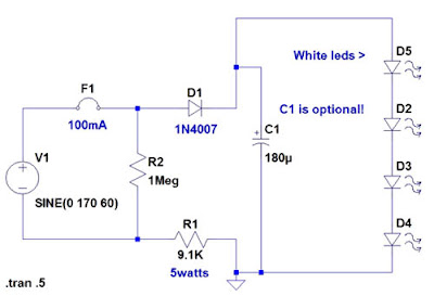
120 Volt 4 LED Light Circuit

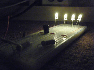
This circuit uses can exist used in the same way as a night light. It uses a 120 V Mains to power the circuit. plant like a charm!

120
Example

120
Circuit Schematic
Parts 
4x - White LEDs
1x - 9.1K 5watt Resistor
1x - 1N4007
1x - 180or220uF 25v cap
1x - 1Meg 1/2watt Resistor
1x - 100mA fuse
1x - Enclosure

If the ac supply is 220 volts,then which resistir should  replace and by which one, 220v is twice of 110v so doubles the value due to the voltage work, try to replace 9k1 with 22k-100k and capasitor voltage 160v.
Read More..