Showing posts with label 12v. Show all posts

Thursday, November 13, 2014

DC motor 12V speed controller circuit with explanation
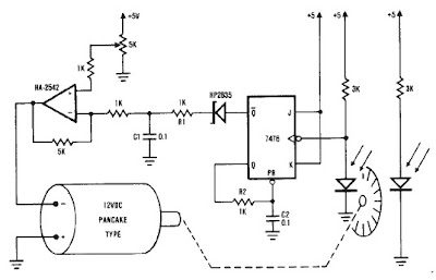
 dc motor 12v speed controller circuit with explanation

A very simple encoder circuit for a dc motor can be constructed using this circuit diagram . As you can see in the circuit diagram , the system shown consists of the HA-2542, a small 12-Vdc motor, and a position encoder. During operation, the encoder causes a series of constant-width" pulses to charge CI. The integrated pulses develop a reference voltage, which is proporţional to motor speed and is applied to the inverting input of HA-2542, The noninverting input is held at a constant voltage, which represents the desired motor speed. A difference between these two inputs will send a corrected drive signal to the motor, which completes the speed control system loop.

As you can see the circuit requires few external components , but because of the encoder wheel it has a limitations of use .If you put a pulley under the encoder wheel you can command the speed of other device , by connecting the (motor and other device ) using a belt

Read More..

Wednesday, September 24, 2014

Simple 12V to 250V Converter

A very simple portable 12v to 250V converter can be designed using this circuit diagram. This 12 to 250V converter is designed for portable use with a 12 V car battery.A built astabil multivibrator T1 and T2 generates a rectangular wave at a frequency of 50 Hz. As T1 and T2 drive alternative exit stage system also works in "push-pull". When T1 lead by passing a current T3: T5 and that it engages the latter transistor connects to a half battery of 12 V secondary winding of the transformer Tr When T2 network drive, T6 transistor coupled to the battery the other half of the network adapter.


 If it is used for output stages 40 411 RCA transistors, the current through secondary winding can be up to 10 A, giving a power output of 180 watts. If you use 2N3055 transistors, power output will be about 90 watts. Since the output transistors are driven to saturation, they have very high mounted radiators.Although circuit is simple construction and has high efficiency disadvantage is rectangular output voltage which, in the absence of a regulator is dependent on task: small loads, the output voltage is 250 V ac (not working properly for the engine speed control, light dimmers, televisions, hi-fi equipment.
Read More..

Thursday, April 4, 2013

12V Speed Controller Dimmer

This handy circuit can be used as a speed controller for a 12V motor rated up to 5A (continuous) or as a dimmer for a 12V halogen or standard incandescent lamp rated up to 50W. It varies the power to the load (motor or lamp) using pulse width modulation (PWM) at a pulse frequency of around 220Hz. SILICON CHIP has produced a number of DC speed controllers over the years, the most recent being our high-power 24V 40A design featured in the March & April 2008 issues. Another very popular design is our 12V/24V 20A design featured in the June 1997 issue and we have also featured a number of reversible 12V designs.

Circuit looks like:

12V-speed-controller-lamp-dimmer-circuit

For many applications though, most of these designs are over-kill and a much simpler circuit will suffice. Which is why we are presenting this basic design which uses a 7555 timer IC, a Mosfet and not much else. Being a simple design, it does not monitor motor back-EMF to provide improved speed regulation and nor does it have any fancy overload protection apart from a fuse. However, it is a very efficient circuit and the kit cost is quite low.

Parts layout:

parts-layout-12V-speed-controller-lamp-dimmer-circuit

Connection diagram:

12V-motor-speed-controller-lamp-dimmer-circuit

There are many applications for this circuit which will all be based on 12V motors, fans or lamps. You can use it in cars, boats, and recreational vehicles, in model boats and model railways and so on. Want to control a 12V fan in a car, caravan or computer? This circuit will do it for you.

Circuit diagram:

12V-speed-controller-lamp-dimmer-circuit-diagram

The circuit uses a 7555 timer (IC1) to generate variable width pulses at about 210Hz. This drives Mosfet Q3 (via transistors Q1 & Q2) to control the speed of a motor or to dim an incandescent lamp.
Halogen lamps: 
 
While the circuit can dim 12V halogen lamps, we should point out that dimming halogen lamps is very wasteful. In situations where you need dimmable 12V lamps, you will be much better off substituting 12V LED lamps which are now readily available in standard bayonet, miniature Edison screw (MES) and MR16 halogen bases. Not only are these LED replacement lamps much more efficient than halogen lamps, they do not get anywhere near as hot and will also last a great deal longer.

Source:  http://www.ecircuitslab.com/2012/01/12v-speed-controllerdimmer.html 
Read More..