Showing posts with label lighting. Show all posts
Showing posts with label lighting. Show all posts
Wednesday, September 24, 2014
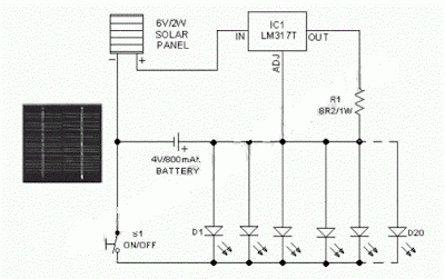
Lighting Garden with Solar Energy Circuit Diagram
This is an economic circuit of a mini solar lighting system, solar panel 6V/2W is used to charge a rechargeable 4V/800mAh through a current limiting circuit load that uses a LM317T adjustable regulator 3 pin (IC1). Assuming a sunny day 6 hours, a panel will enviarr 2 watts for approximately 900mAh battery. The current can be reduced by increasing the value of R1, for example, 8.2 to 10 ohms ohms.
Lighting Garden with Solar Energy Circuit Diagram
Spec of a typical solar panel
6V/2W:Maximum power (Pm):
2WWorking Voltage (Vmp):
9VWorking Current (Imp):
220mAOpen Circuit Voltage (Voc):
10.5VPower Tolerance: -3% to 5%

Sunday, April 7, 2013
LED Workbench Lighting
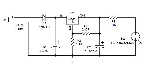
Here is a very useful workbench lighting unit for electronics hobbyists. The portable inspection lamp circuit consists of an on-board voltage regulator and a high-bright 5mm white LED. Any 9 to 18 volt dc rated ac mains adaptor, capable to source about 100 mA of output current can be used to power this portable inspection lamp.
After construction the led workbench light circuit should be enclosed in a suitable plastic bottle cap as illustrated here. The miniature lens shown is an optional component. In the prototype, plastic made lens lifted from a discarded torch was used!
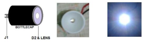
After construction the led workbench light circuit should be enclosed in a suitable plastic bottle cap as illustrated here. The miniature lens shown is an optional component. In the prototype, plastic made lens lifted from a discarded torch was used!
LED workbench lighting lamp circuit schematic
http://schematicm.blogspot.com/
Subscribe to:
Posts (Atom)