Showing posts with label led. Show all posts

Tuesday, November 18, 2014

Automatic LED Emergency Light


Description
This is the circuit diagram of a low cost emergency light based on white LED.The white LED provide very bright light which turns on when the mains supply is not there.The circuit has an automatic charger which stops charging when the battery is fully charged.

The IC LM 317 produces a regulated 7 V for the charging of Battery.Transistor BD 140 drives the out put.Transistor BC 548 and Zener diode controls the charging of the battery.

Tips
It is always better to connect a heat sink with BD 140.Before using the circuit out put of LM317 must be set to 7V by adjusting the potentiometer.
Read More..

Sunday, November 9, 2014

Build LED Light Pen Schematic

Physicians and repair engineers often use small light pens for visual examination purposes. Rugged and expensive as these pens may be, their weak point is the bulb, which is a ‘serviceable’ part. In practice, that nearly always equates to ‘expensive’ and / or ‘impossible to find’ when you need one.

LEDs have a much longer life than bulbs and the latest ultra bright white ones also offer higher energy-to-light conversion efficiency. On the down side, LEDs require a small electronic helper circuit called ‘constant-current source’ to get the most out of them.
 
LED Light Pen Circuit Diagram
LED-Light-Pen-Circuit-Diagram

Here, T1 and R1 switch on the LED. R2 acts as a current sensor with T2 shunting off (most of) T1’s base bias current when the voltage developed across R2 exceeds about 0.65 V. The constant current through the white LED is calculated from

R2 = 0.65 / ILED
With some skill the complete circuit can be built such that its size is equal to an AA battery. The four button cells take the place of the other AA battery that used to be inside the light pen.
Read More..

Saturday, November 1, 2014

120 Volt 4 LED Light Circuit

This circuit uses can exist used in the same way as a night light. It uses a 120 V Mains to power the circuit. plant like a charm!

120
Example

120
Circuit Schematic
Parts 
4x - White LEDs
1x - 9.1K 5watt Resistor
1x - 1N4007
1x - 180or220uF 25v cap
1x - 1Meg 1/2watt Resistor
1x - 100mA fuse
1x - Enclosure

If the ac supply is 220 volts,then which resistir should  replace and by which one, 220v is twice of 110v so doubles the value due to the voltage work, try to replace 9k1 with 22k-100k and capasitor voltage 160v.
Read More..

Wednesday, October 15, 2014

LED light Organ Circuit Diagram

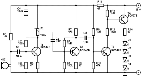
This is a fun circuit that can be at parties, for example. The four LEDs flash to the beat of the music. The light organ responds using a microphone to sound.T1 amplifies the signal from MIC. The sensitivity can be adjusted by P1. T4 controls the LEDs. 

These are preferably LEDs with a high light intensity.MIC is a condenser microphone. The circuit can be powered by a 9 V battery.

 LED light Organ Circuit Diagram

 led light organ circuit diagram


The 4 Budget

This circuit costs about € 6.15.


Parts List

  •      R1 = 10 k
  •      R2 = 330 K?
  •      R3, R6, R13 = 100 k
  •      R4, R8, R11, R14 = 47 Ω
  •      R5, R9, R12 = 1.5 MΩ
  •      R7, R10 = 47 k
  •      P1 = 220 K?
  •      C1, C2, C3 = 100 nF
  •      C4 = 100 uF
  •      D1-D4 = LED
  •      T1, T2, T3 = BC547B
  •      T4 = BC557B
  •      MIC = microphone capsule
Read More..

Wednesday, September 24, 2014

Bridge Rectifier LED Indicator

Using a few diodes and a LED, you can make a nice indicator as shown in associated schematic diagram that can be used for a lot of applications (with a bit of luck). It’s quite suitable for use in series with a doorbell or thermostat (but don’t try to use it with an electronically con-trolled central-heating boiler!). This approach allows you to make an attractive indicator for just a few pennies.

Bridge-Rectifier-LED-Indicator image

The AC or DC current through the circuit causes a voltage drop across the diodes that is just enough to light the LED. As the voltage is a bit on the low side, old-fashioned red LEDs are the most suitable for this purpose. Yellow and green LEDs require a somewhat higher forward voltage, so you’ll have to first check whether it works with them. Blue and white LEDs are not suitable. You also don’t have to use modern high-efficiency types (sometimes called ‘2-mA LEDs’ or ‘3-mA LEDs’). If a DC current flows through the circuit and the LED doesn’t light up, reverse the plus and minus leads.

Circuit diagram :

Bridge-Rectifier-LED-Indicator-Circuit-Diagram

Bridge-Rectifier  LED Indicator Circuit Diagram

When building the circuit, you’ll notice that despite its simplicity it involves fitting quite a few components to a
small printed circuit board or a bit of prototyping board. That’s why we’d like to give you the tip of using a bridge rectifier, since that allows everything to be made much more compact, smaller and more tidy, and it eliminates the need for a circuit board to hold the components. Besides that, you can surprise friend and foe alike, because even an old hand in the trade won’t understand the trick at first glance and will likely mumble something like “Huh?
That’s impossible.”

A bridge rectifier contains four diodes, which is exactly what you need. If you short the + and – terminals of the bridge, you create a circuit with two pairs of diodes connected in parallel with oppo-site polarity. Select a bridge rectifier that can handle the current that will flow through it. In the case of a doorbell, for example, that can easily be 1 A. Select a voltage of 40 or 80 V.

Never use this circuit in combination with mains voltage, due to the risk of contact with a live lead. 


Ecircuitslab.com
Read More..

LED Flasher for Cars and Motorcycles Circuit Diagram

This is a flasher that uses 4 high brightness LEDs that can be used in Automotive, Motorcycle or bicycle. It uses the IC 555 which is a monostable to adjust the flasher you can use the RV1, which can be a potentiometer or trim pot 100k. If built in SMD it fits within the own flashlight.

 LED Flasher for Cars and Motorcycles Circuit Diagram

LED Flasher for Cars and Motorcycles Circuit Diagram

Read More..

Wednesday, June 12, 2013

Philips LED Queen Star light bulbs in Taiwan officially listed

Recently, the worlds first won the U.S. Energy Star Queen Star of Philips LED bulb is officially on sale in Taiwan. This section bulb uses 300-degree ultra-wide-angle lighting, 825 lumens, 2700K color temperature, 80% of CRI, 12W power consumption, the highest life expectancy of 25,000 hours (six hours a day, you can use 11.4 years).


Bo Jiansheng of the general manager of Philips Taiwan said that the development of green technology is the most important global issues, green sustainable development is an important core value of the Philips, Philips attaches great importance to lighting technology to enhance the quality of human life, improve energy efficiency, and practice green ecological concept, to bring comfort and quality of life of the public health.


Recently, the worlds first won the U.S. Energy Star Queen Star of Philips LED bulb is officially on sale in Taiwan. This section bulb uses 300-degree ultra-wide-angle lighting, 825 lumens, 2700K color temperature, 80% of CRI, 12W power consumption, the highest life expectancy of 25,000 hours (six hours a day, you can use 11.4 years).

Philips accounted for nearly 40 percent of the global LED light bulb market, Philips LED Queen Star has more than one million sales in the world, has made the international IEC eye certification, the German iF design awards, Time magazine boutique Medal U.S. Department of Energy L-Prize, energy-efficient lighting awards international awards.
Read More..

Tuesday, May 28, 2013

AC powered LED Indicator

This is an indicator you can use this circuit with your Ac electronic items.Here I have used normal Led.Attach purple color connections to the AC line.I suppose this will be a wonderful circuit for you.

Note
# This is not a good circuit for kids Because here we use 230V So dont try to build this.
# Build this circuit on a PCB
Read More..

Saturday, April 13, 2013

Low Power LED Battery Voltmeter Schematic


This is a low power voltmeter circuit that can be used with alternative energy systems that run on 12 and 24 volt batteries. The voltmeter is an expanded scale type that indicates small voltage steps over the 10 to 16 volt range for 12 volt batteries and over the 22 to 32 volt range for 24 volt batteries. Power consumption can be as low as 14mw when operated from 12V and 160mw when operated from 24V. It is possible to set the meter to read equal steps across a variety of upper and lower voltages. The meter saves power by operating in a low duty-cycle blinking mode where the LED indicators are only on and consuming power briefly during a repeating 2 second cycle. The circuit may be switched to a high power mode where the active LED stays on at all times.

Different colored LEDs may be used for the voltage level indicator, this allows the battery state to be read in the dark. With the new blue LEDs, it is possible to have a nice looking rainbow of colors using two each of red, amber, yellow, green, and blue LEDs. The circuit will also work with inexpensive and common red LEDs. If the circuit is to be used in sunlight, ultra-bright LEDs should be used, although even those may be hard to read without some kind of sun shield. The circuit may be built with either the CMOS ICM7555 timer or the more common bipolar 555 timer. The 7555 timer will provide much more efficient operation and should be used for systems with small batteries.

Theory for 12 Volt operation
The heart of the circuit is the LM3914N dot-bar volt meter IC, U2. This chip is operated in the expanded-scale mode so that the circuit responds in the 10-16V range. U2 outputs a steady voltage on pin 7 from the internal voltage reference. This is fed via voltage dividers VR2 and R5 to the internal reference input pins to set the range that the meter is sensitive to. The measured voltage is fed in on pin 5 via the voltage divider consisting of R4 and VR1. This divider scales the input voltage down to a range that is useful to the IC.

The U2 positive supply is connected to pin 3 which is nominally 12V. The U2 negative supply is switched on momentarily via transistor Q1, this switching action is what makes the circuit efficient since U1 (ICM7555) consumes a mere 0.34 ma while U2 consumes around 18ma with one LED on. The ICM7555 timer, U1 is wired to run in a free-running mode with a narrow pulse width square wave output.

The duty-cycle of U1 is controlled by the ratio of R1 and R2. R2 may be adjusted to a smaller value if faster blinking is desire, a potentiometer may be substituted for R2 if a rate adjustment is desired. R1 may be increased if a longer on-time is desired. Changes in R1 and R2 will affect the average current that the circuit consumes. The frequency of oscillation is determined by C1, R1, and R2. C1 may be either an electrolytic or poly capacitor, if an electrolytic part is used, be sure to connect the positive terminal to U1 pins 6 and 2 and the negative terminal to ground.

The output of the timer IC is fed through current limiting resistor R3 to transistor Q1 which controls power to U2. Capacitor C2 filters the control voltage input to U1 and capacitor C3 provides DC filtering for the whole circuit. When the lock-on switch across capacitor C1 is closed, the output of the timer remains on, thus enabling the U2 circuitry and increasing the current drain to 18mA. The reason the switch is not simply wired across the transistor is to keep the negative supply to U2 the same as when the circuit is pulsed on. This maintains the same calibration on the LEDs in both modes because the transistors voltage drop is always part of the circuit.

Last, but not least, fuse F1 protects against the potential for fire hazard should the circuit become shorted out. The average current is calculated by adding the constant current required by U1 with the product of the current from U2 times the duty cycle, see the specifications for details. To operate the circuit in the 12V mode, wire the circuit so that jumpers J2 and J5 are shorted, parts U3, C4, R6, and R7 may be left out.

Theory for 24 Volt operation
When wired for 24 Volt operations, the meter responds in the 20-32V range. R6 is connected to the 24V supply instead of R4, the greater value of R6 scales the higher input voltage to a range that is useful for U2. Voltage regulator U3 with series resistor R7 scales the 24V down to a regulated 12V to provide the proper operating voltage for the ICs. Resistor R7 assures that the input voltage to the regulator stays well below the 35V absolute maximum specification of the IC. Operation in 24V mode is less efficient than in 12V mode because of the extra power dissipated by the voltage regulator and R7. To operate the circuit in the 24V mode, wire the circuit so that jumpers J1, J3, and J4 are shorted. R4 may be left out in the 24V mode.

Read More..

Sunday, April 7, 2013

LED Workbench Lighting

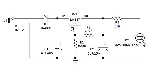
Here is a very useful workbench lighting unit for electronics hobbyists. The portable inspection lamp circuit consists of an on-board voltage regulator and a high-bright 5mm white LED. Any 9 to 18 volt dc rated ac mains adaptor, capable to source about 100 mA of output current can be used to power this portable inspection lamp.

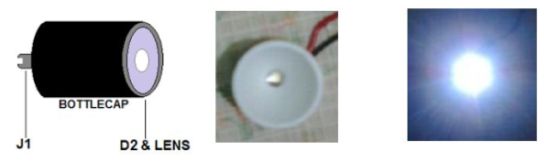
After construction the led workbench light circuit should be enclosed in a suitable plastic bottle cap as illustrated here. The miniature lens shown is an optional component. In the prototype, plastic made lens lifted from a discarded torch was used!
Circuit Project: LED workbench lighting

LED workbench lighting lamp circuit schematic
Circuit Project: LED workbench lighting
The adjustable 3-pin voltage regulator IC1 (LM317L) in TO-92 pack, is here tuned to supply an output of near 4.5 volt dc. This supply is directly fed to the white LED (D2) through the current limiter resistor R3 (51 Ohm). Diode D1 (1N4001) works as an input polarity protection guard and two small electrolytic capacitors (C1 and C2) connected at the input and output pins of IC1 improves the overall stability of the regulator circuit. Use a standard RCA or EP socket as the input terminal J1.
                                                                                                                http://schematicm.blogspot.com/
Read More..