Monday, October 13, 2014
2N3055 Variable DC Power Supply circuit Diagram
Voltage range: 0.7 – 24V Current limiting range: 50mA – 2A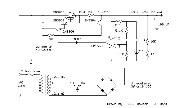
A Variable DC Power Supply is one of the most useful tools on the electronics hobbyist’s workbench. This circuit is not an absolute novelty, but it is simple, reliable, “rugged” and short-proof, featuring variable voltage up to 24V and variable current limiting up to 2A. Well suited to supply the circuits shown in this website. You can adapt it to your own requirements as explained in the notes below.
Notes:
* P1 sets the maximum output current you want to be delivered by the power supply at a given output voltage.
* P2 sets the output voltage and must be a logarithmic taper type, in order to obtain a more linear scale voltage indication.
* You can choose the Transformer on the grounds of maximum voltage and current output needed. Best choices are: 36, 40 or 48V center-tapped and 50, 75, 80 or 100VA.
* Capacitor C1 can be 2200 to 6800µF, 35 to 50V.
* Q4 must be mounted on a good heatsink in order to withstand sustained output short-circuit. In some cases the rear panel of the metal box in which you will enclose the circuit can do the job.
* The 2N3055 transistor (Q4) can be replaced with the slightly less powerful TIP3055 type.
Parts:
P1____________500R Linear Potentiometer
P2_____________10K Log. Potentiometer
R1,R2___________2K2 1/2W Resistors
R3____________330R 1/4W Resistor
R4____________150R 1/4W Resistor
R5______________1R 5W Resistor
C1___________3300µF 35V Electrolytic Capacitor (see Notes)
C2______________1µF 63V Polyester Capacitor
D1,D2________1N5402 200V 3A Diodes
D3_____________5mm. Red LED
Q1____________BC182 50V 100mA NPN Transistor
Q2____________BD139 80V 1.5A NPN Transistor
Q3____________BC212 50V 100mA PNP Transistor
Q4 __________2N3055 60V 15A NPN Transistor
T1_____________220V Primary, 36V Center-tapped Secondary
50VA Mains transformer (see Notes)
PL1____________Male Mains plug
SW1____________SPST Mains switch

Wednesday, September 24, 2014
Deriving High Current from 7805 7812 Voltage Regulator Power Supply Citcuits
- If, for instance, a power transistor is connected in parallel with the IC, the supply will no longer be protected against short-circuits.

- The circuit given here shows that a simpler solution is possible: the power transistor, T1, is provided with an emitter resistor! This effectively solves the problem, because the current through Tl is then proportional to the current supplied by the voltage regulator.
- But this solution A suffers from a heavy power loss during short-circuit conditions, which is not really acceptable either.
- There are various ways and means of drawing more current from a voltage regulator IC than it was originally intended to supply, but most methods have their disadvantages.
- lf the 7805 or 7812 regulator and T1 are mounted onto the same heatsink, the transistor is also thermally protected! The output voltage is dependent only on the type of voltage regulator used and, as drawn here, the circuit is suitable for currents up to 2 A.
- lf higher values are required, some components need to be changed according to the table. For currents above 7 A, transistor T1 must be replaced by two parallel-connected transistors each of which has an emitter resistor, R1 and R1 respectively.
- That can, of course, be remedied by adding a current sensor in the shape of an extra transistor which, during overload conditions, cuts off the base current to the power transistor.

Monday, September 1, 2014
Multiple output switching power supply circuit
This power supply uses two VN400A 400 Volts MOSFETs in a half-bridge power switch configuration. Each output consists of +5V at 20 A and 15 V at 1 A . Three-terminal regulators are used for the low-currents outputs , either 12 Volts or 15 Volts can be made available with a simple change in the transformer secondary windings. Schematic diagram below :

IC TL494 switching regulator IC provides pulse-with modulation control and drive signals for the power supply , The upper MOSFET , Q7 , in the power switch stage is driven by a simple transformer drive circuit. The lower MOSFET , Q6 , since it ground referenced , is directly driven from the control IC.
Saturday, August 30, 2014
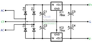
Constructing your own Dual Power Supply Rise
Note that the + & - regulators do not must be matched: you can for example, use a +5v & -9V pair. However,the positive regulator must be a 78xx regulator, & the negative a 79xx. They have built in plenty of safety in to this project so it ought to give plenty of years of continuous service.
This Dual Power Supply design makes use of a full wave bridge rectifier coupled with a centre-tapped transformer. A transformer with a power output rated at at least 7VA ought to be used. The 7VA rating means that the maximum current which can be delivered without overheating will be around 390mA for the 9V+9V tap; 290mA for the 12V+12V and 230mA for the 15V+15V. If the transformer is rated by output RMS-current then the worth ought to be divided by one.2 to get the current which can be supplied. For example, in this case a 1A RMS can deliver 1/(one.2) or 830mA.
The purpose of the filter capacitor is to smooth out the ripple in the rectified AC voltage. Theres dual amount of ripple is determined by the worth of the filer capacitor: the larger the worth the smaller the ripple.The two,200uF is an appropriate value for all the voltages generated using this project. The other consideration in choosing the correct capacitor is its voltage rating. The working voltage of the capacitor has to be greater than the peak output voltage of the rectifier. For an 18V supply the peak output voltage is one.4 x 18V, or 25V. So they have selected a 35V rated capacitor.

Wednesday, August 27, 2014
Offline Switching Power Supply Circuit 5V 10A 50W
Circuit Diagram:

Parts List:

This switching power supply is using a MOSFET. For 220V AC voltage input, use BUZ80A/IXTP4N8 MOSFET and for 110V AC input voltage, use GE IRF823 MOSFET. The output will be 5 Volt DC with electric current can be reach 10A.
Wednesday, May 29, 2013
Power Supply Monitor Using LM3914

This circuit is useful where quick and easy voltage adjustments must be made, such as in the field or on the production line. The circuit’s low cost makes it feasible to incorporate it into the system, where the overvoltage and under voltage warning signals provide an attractive extra. Of course, these techniques can be used to monitor any higher voltages, positive or negative. Calibration procedure is the LM3914 output thresholds have been shifted up by 100 mV and output #10 is or-tied with output #9. Other outputs may be wire or together if 100 mV resolution is not necessary. If desired, the outputs can be color coded by making LED #1 and LED #10 red, LED #2 and LED #9 amber, and the rest of the LEDs green to ease interpretation.
To calibrate, set VCC at 5.41V and adjust R6 until LED #9 and LED #10 are equally illuminated. (A built-in overlap of about 1 mV ensures all LEDs won’t go out at a threshold point.) There’s no need to vary the system supply voltage to perform this adjustment. Instead, disconnect R1 from VCC and connect it to an accurate reference. Then, at 4.5V, adjust R4 until LED #1 just barely turns on. There is a slight interaction caused by the finite resistance (10k, type) of the LM3914’s voltage divider, so that repeating the above procedure once is advised. The LED driver outputs can directly drive a TTL gate, so that the LED #1 and LED #10 outputs may be used for under voltage and overvoltage warning signals. These may be used to initiate a soft shutdown or summon an operator, for example. The 470Ω resistor R8 ensures that the LM3914 output will saturate to provide the proper TTL low level. Pull-up resistor R9 provides the logic high level.
Tuesday, April 30, 2013
1 5 35 Volt DC Regulated Power Supply
Picture of the circuit:


IC = LM317
P1 = 4.7K
R1 = 120R
C1 = 100nF - 63V
C2 = 1uF - 35V
C3 = 10uF - 35V
C4 = 2200uF - 35V
D1-D4 = 1N4007
Features:
- Just add a suitable transformer (see table)
- Great to power your projects and save money on batteries
- Suitable as an adjustable power supply for experiments
- Control DC motors, low voltage light bulbs, …
- Preset any voltage between 1.5 and 35V
- Very low ripple (80dB rejection)
- Short-circuit, thermal and overload protection
- Max input voltage : 28VAC or 40VDC
- Max dissipation : 15W (with heatsink)
- Dimensions : 52x52mm (2.1” x 2.1”)
- Input Voltage = 40Vdc max Transformer
- Output Voltage = 1.5V to 35Vdc
- Output Current = 1.5 Amps max.
- Power Dissipation = 15W max (cooled)
- It has not to be cooled if used for small powers. 28 Volt AC max is allowed for the input voltage.
Friday, April 5, 2013
Power Supply with regulation
 Electronic devices should be powered by direct current supply of DC (direct current) which is stable in order to work properly. The battery or batteries are the source DC power supply is best. However, for applications that require power supplies larger, the source of the battery is not enough.