Showing posts with label battery. Show all posts

Wednesday, November 19, 2014

Battery Charger based on AVR ATMega 8535

Battery Charger in general can be interpreted as a means to recharge the battery charge. Principles of good charger circuit is capable of providing resources to perform effectively charging the battery, efficient and safe. AVR-Based Battery Charger ATMega 8535 With LCD Display This is an idea that had just emerged from the author. In AVR-Based Battery Charger design ATMega 8535 With LCD Display is using AVR microcontroller processor charger with ATMega 8535, process the data viewer charger with LCD, a safety from a hot temperature with the temperature sensor LM35 and several buttons for setting the charger. And component power charger Battery Charger Based on AVR ATMega 8535 With LCD Display is a FET.

Battery


Function-Based Battery Charger Part Series AVR ATMega 8535 With LCD Display
ATMega 8535 AVR microcontroller serves as the controlling process of the charger.
Button S1 - S5 as input data charger settings (setting the current, maximum temperature, peak voltage batteries)
LM35 Temperature Sensor function as heat sensors in the battery during charge.
LCD Display function to display data and display settings charger battery charger process measurement data.
FET serves as a power charger that will flow into the battery charging current.
Read More..

Saturday, November 8, 2014

Battery Switch With Low Dropout Regulator

In the form of the LT1579 Linear Technology (www.linear-tech.com) has produced a practical battery switch with an integrated low-dropout regulator. In contrast to previous devices no diodes are required. The circuit is available in a 3.3 V version (LT1579CS8-3.3) and in a 5 V version (LT1579CS8-5), both in SO8 SMD packages. There is also an adjustable version and versions in an SO16 package which offer a greater range of control and drive signals. The main battery, whose terminal voltage must be at least 0.4 V higher than the desired output voltage, is connected to pin IN1. The backup battery is connected to pin IN2. The regulated output OUT can deliver a current of up to 300 mA. The LDO regulator part of the IC includes a pass transistor for the main input voltage IN1 and another for the backup battery on IN2.

Battery_Switch_With_LDO_Regulator_Circuit_Diagramw


The IC will switch over to the backup battery when it detects that the pass transistor for the main voltage input is in danger of no longer being able to maintain the required output voltage. The device then smoothly switches over to the backup battery. The open-drain status output BACKUP goes low to indicate when this has occurred. When neither battery is able to maintain the output voltage at the desired level the open-drain output DROPOUT goes low. The LT1579 can operate with input voltages of up to +20 V from the batteries. The regulator output OUT is short-circuit proof. The shutdown input switches off the output; if this feature is not required, the input can simply be left open.
Read More..

Wednesday, September 24, 2014

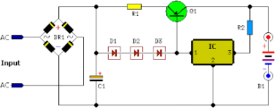
Simple Battery Charger Vehicle Circuit Diagram

Unlike many boots, this battery charger continuously charges the maximum current, decreasing only near full battery voltage. In this case the full load current source, transformer / rectifier was 4.4A. It tapers to 4A 13.5V, 14.0V 3A, 2A 14.5V and 15.0V in 0A.


Simple Battery Charger Vehicle Circuit Diagram

Simple Battery Charger Vehicle Circuit Diagram


Parts:

Resistors
R1 = 0.32R
R2 = 8.2R Capacitors
C1 = x 10,000 uF 63V
D1 = 1N4004
D2 = 1N4004
D3 = 1N4004
Q1 = MJ1504
IC REG = 7815
BR1 = 1N4004x4
B1 = 12 Volt Battery
TR 20 volts AC

R1 and R2 are as high power resistor 2W, 3W, 5W or higher. Q1 and IC requires a heatsink good. If they are mounted on the same heatsink and will decrease the circuit turns Q1 gets too hot.
Read More..

Saturday, April 13, 2013

Low Power LED Battery Voltmeter Schematic


This is a low power voltmeter circuit that can be used with alternative energy systems that run on 12 and 24 volt batteries. The voltmeter is an expanded scale type that indicates small voltage steps over the 10 to 16 volt range for 12 volt batteries and over the 22 to 32 volt range for 24 volt batteries. Power consumption can be as low as 14mw when operated from 12V and 160mw when operated from 24V. It is possible to set the meter to read equal steps across a variety of upper and lower voltages. The meter saves power by operating in a low duty-cycle blinking mode where the LED indicators are only on and consuming power briefly during a repeating 2 second cycle. The circuit may be switched to a high power mode where the active LED stays on at all times.

Different colored LEDs may be used for the voltage level indicator, this allows the battery state to be read in the dark. With the new blue LEDs, it is possible to have a nice looking rainbow of colors using two each of red, amber, yellow, green, and blue LEDs. The circuit will also work with inexpensive and common red LEDs. If the circuit is to be used in sunlight, ultra-bright LEDs should be used, although even those may be hard to read without some kind of sun shield. The circuit may be built with either the CMOS ICM7555 timer or the more common bipolar 555 timer. The 7555 timer will provide much more efficient operation and should be used for systems with small batteries.

Theory for 12 Volt operation
The heart of the circuit is the LM3914N dot-bar volt meter IC, U2. This chip is operated in the expanded-scale mode so that the circuit responds in the 10-16V range. U2 outputs a steady voltage on pin 7 from the internal voltage reference. This is fed via voltage dividers VR2 and R5 to the internal reference input pins to set the range that the meter is sensitive to. The measured voltage is fed in on pin 5 via the voltage divider consisting of R4 and VR1. This divider scales the input voltage down to a range that is useful to the IC.

The U2 positive supply is connected to pin 3 which is nominally 12V. The U2 negative supply is switched on momentarily via transistor Q1, this switching action is what makes the circuit efficient since U1 (ICM7555) consumes a mere 0.34 ma while U2 consumes around 18ma with one LED on. The ICM7555 timer, U1 is wired to run in a free-running mode with a narrow pulse width square wave output.

The duty-cycle of U1 is controlled by the ratio of R1 and R2. R2 may be adjusted to a smaller value if faster blinking is desire, a potentiometer may be substituted for R2 if a rate adjustment is desired. R1 may be increased if a longer on-time is desired. Changes in R1 and R2 will affect the average current that the circuit consumes. The frequency of oscillation is determined by C1, R1, and R2. C1 may be either an electrolytic or poly capacitor, if an electrolytic part is used, be sure to connect the positive terminal to U1 pins 6 and 2 and the negative terminal to ground.

The output of the timer IC is fed through current limiting resistor R3 to transistor Q1 which controls power to U2. Capacitor C2 filters the control voltage input to U1 and capacitor C3 provides DC filtering for the whole circuit. When the lock-on switch across capacitor C1 is closed, the output of the timer remains on, thus enabling the U2 circuitry and increasing the current drain to 18mA. The reason the switch is not simply wired across the transistor is to keep the negative supply to U2 the same as when the circuit is pulsed on. This maintains the same calibration on the LEDs in both modes because the transistors voltage drop is always part of the circuit.

Last, but not least, fuse F1 protects against the potential for fire hazard should the circuit become shorted out. The average current is calculated by adding the constant current required by U1 with the product of the current from U2 times the duty cycle, see the specifications for details. To operate the circuit in the 12V mode, wire the circuit so that jumpers J2 and J5 are shorted, parts U3, C4, R6, and R7 may be left out.

Theory for 24 Volt operation
When wired for 24 Volt operations, the meter responds in the 20-32V range. R6 is connected to the 24V supply instead of R4, the greater value of R6 scales the higher input voltage to a range that is useful for U2. Voltage regulator U3 with series resistor R7 scales the 24V down to a regulated 12V to provide the proper operating voltage for the ICs. Resistor R7 assures that the input voltage to the regulator stays well below the 35V absolute maximum specification of the IC. Operation in 24V mode is less efficient than in 12V mode because of the extra power dissipated by the voltage regulator and R7. To operate the circuit in the 24V mode, wire the circuit so that jumpers J1, J3, and J4 are shorted. R4 may be left out in the 24V mode.

Read More..

Friday, April 5, 2013

Battery Charger based on AVR ATMega 8535

Battery Charger in general can be interpreted as a means to recharge the battery charge. Principles of good charger circuit is capable of providing resources to perform effectively charging the battery, efficient and safe. AVR-Based Battery Charger ATMega 8535 With LCD Display This is an idea that had just emerged from the author.
In AVR-Based Battery Charger design ATMega 8535 With LCD Display is using AVR microcontroller processor charger with ATMega 8535, process the data viewer charger with LCD, a safety from a hot temperature with the temperature sensor LM35 and several buttons for setting the charger. And component power charger Battery Charger Based on AVR ATMega 8535 With LCD Display is a FET.
Click to view larger

Function-Based Battery Charger Part Series AVR ATMega 8535 With LCD Display
ATMega 8535 AVR microcontroller serves as the controlling process of the charger.
Button S1 - S5 as input data charger settings (setting the current, maximum temperature, peak voltage batteries)
LM35 Temperature Sensor function as heat sensors in the battery during charge.
LCD Display function to display data and display settings charger battery charger process measurement data.
FET serves as a power charger that will flow into the battery charging current.
Read More..