Showing posts with label electronic. Show all posts
Showing posts with label electronic. Show all posts
Thursday, November 13, 2014
NJM2582 bassed 4 channel video amplifier electronic project circuit with explanation
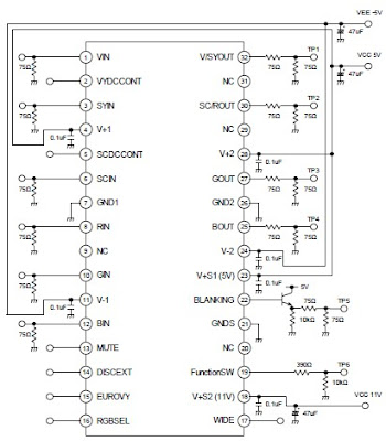
A very simple 4 channel video amplifier electronic circuit project can be designed using NJM2582 ic suitable for video applications with SCART connector . Design of the circuit is very simple and require few external electronic parts .
Some features of the NJM2582 are : Operating Voltage ±5V, +5V, +11V ; 6input 4output , 2input 1output Video SW , Internal LPF , 6dB Amplifier , Internal 75Ω Driver Circuit , DC output for SCART (FUNCTION SW, BLANKING) .

Monday, November 3, 2014
YAMAHA R5C 350 ELECTRONIC DIAGRAM

YAMAHA R5C 350 ELECTRONIC DIAGRAM
It shows the connection between the parts such as the front flasher light, rear flasher light, flasher relay, battery, fuse, tail light, stop light, rear flasher light, rear stop switch, neutral switch, front stop switch, AC generator, coil, rectifier, regulator, horn, head light, tachometer, speedometer, high beam indicator light, rear flasher, front flasher, and many more.
Sunday, November 2, 2014
ALTERNATING FLASHER ELECTRONIC DIAGRAM

ALTERNATING FLASHER ELECTRONIC DIAGRAM
The first IC used as a 1 second clock, which generates ON/OFF for the other ICs. Diodes help to cover the IC555 from the peak voltage. Take note that the relay used should have impedance more than 50 ohm.
Parts list :
- Diode D1-D2 : 1N4001
- Zener Diode D2 : 6V
- R1,R5,R7 : 3k3
- R2,R6,R8 : 68k
- Resistor variable VR1 : 47k
- Polar capacitor C1 : 10uF/16V
- Polar capacitor C3,C5 : 2.2 uF/16V
- Capacitor C2,C4,C6 : 0.01 uF
- Transistor T1 : BC107/BC148
- IC timer : NE555
- Relay : 6-9 V
- Power supply 6-9 V
Friday, October 10, 2014
NCP2824 Class D amplifier electronic project circuit and explanation
Using the NCP2824 filterless Class D amplifier can be designed a very simple low power audio amplifier electronic project, capable of delivering up to 2.4 W to a 4 ohms load with a 5 V supply voltage.
With the same battery voltage, it can deliver 1.2 W to an 8 ohms load with less than 1% THD+N. The non−clipping function automatically adjusts the output voltage in order to control the distortion when an excessive input is applied to the amplifier.
This adjustment is done thanks to an Automatic Gain Control circuitry (AGC) built into the chip. A simple single wire interface allows to the non Clipping function to be enabled and disabled.
A programmable power limit function is also embedded in order to protect speakers from damage caused by an excessive sound level.
Wednesday, September 24, 2014
Simple Electronic Door Lock Circuit Diagram
Its easy to build and straight forward. This electronic door lock has a remarkable conception because it uses only one active component. How does it work?
Electronic Door Lock Circuit Diagram

To put the relay in tension the 4 buttons S1 – S4 must be pressed. If anyone of the 4 butoons S5 – S8 are pushed the relay doesn’t switch. The supply voltage must be equal to the working voltage of the relay. One transistor like BD135 can switch up to 0.5A, at the same time 2N2222 can do only 0.2A.
Electronic Door Lock Circuit Diagram

To put the relay in tension the 4 buttons S1 – S4 must be pressed. If anyone of the 4 butoons S5 – S8 are pushed the relay doesn’t switch. The supply voltage must be equal to the working voltage of the relay. One transistor like BD135 can switch up to 0.5A, at the same time 2N2222 can do only 0.2A.
Simple Horn Bugle Electronic Circuit Diagram
This Simple Horn Bugle Electronic Circuit Diagram just a door trigger input 4093, bound in a low frequency oscillator, as the transistor Q1, which is the IRF511 FET amplifier is directly connected to a small speaker with horn. The output frequency can be changed by adjusting potentiometer R1.
Simple Horn Bugle Electronic Circuit Diagram

Sunday, April 7, 2013
HONDA CB100 ELECTRICAL MOTORCYCLE ELECTRONIC DIAGRAM

HONDA CB100 Electrical MOTORCYCLE ELECTRONIC DIAGRAM
Honda parts such as the headlight control switch, front stop switch, main switch, rear stop switch, selenium rectifier, wire harness coupler, ground to frame, right rear turn signal light, tail/stop light, left rear turn signal light, fuse, battery, winker relay, neutral switch, ac generator, condenser, contact breaker, ignition coil, dc horn, spark plug, turn signal control/horn switch, headlight control switch arrangement, left front turn signal light, headlight, high beam indicator light, turn signal indicator, neutral indicator, and also the color code.
Subscribe to:
Posts (Atom)