Showing posts with label ic. Show all posts

Wednesday, November 5, 2014

Programming The Propeller IC

Parallax, well known for its successful Basic Stamp IC, has recently introduced the Propeller: a new microcontroller with a certain difference. It packs no less than eight 32-bit processors (referred to as COGs in Propeller jargon) into a single package with only 40 pins. That design takes genuine simultaneous multiprocessing possible, and the sophisticated internal structure of the device makes it relatively easy to implement video and signal-processing applications. The Propeller can be programmed in assembly language or the high-level Spin language. The processor and the programming tools were developed entirely in-house by Parallax, with the hardware being designed from scratch starting at the transistor level.

Circuit diagram:
programming-the-propeller-ic-circuit-diagramw
Programming The Propeller IC Circuit Diagram

The basic idea behind that was to avoid becoming involved in all sorts of patent disputes with other manufacturers. The result is astounding, and for software developers it certainly requires a change in mental gears. As is customary with modern microprocessors, the Propeller has a simple serial programming interface. The developer’s toolkit from Parallax has a modern USB port for that purpose, but a reasonably simple alternative (illustrated here) is also possible for anyone who prefers to work with the familiar RS232 port. Don’t forget that the Propeller works with a 3.3-V supply voltage.
Read More..

Thursday, October 9, 2014

latest Light Detector by IC CD4001 circuit and explanation

Variable resistor R1 adjusts the light threshold at which the circuit triggers. R1’s value is chosen to match the photocells resistance at darkness. The circuit uses a CMOS 4001 IC. Gate U1a acts as the trigger, U1b and c form a latch. S1 resets the circuit. The output device may be a low power piezo buzzer.

Kindly submitted by Mick Devine from the UK 

Read More..

Wednesday, September 24, 2014

How to Treble and Bass Control without IC or Transistor

This Treble and Bass Control without IC or Transistor circuit consists of bass and treble just a few capacitors, resistors and two potentiometers to adjust BASS and TREBLE. The circuit is very functional, can be used to adjust the small sound amplifiers. And control Treble and works relatively well. The interesting thing is that this control does not use or IC or transistor.

Treble and Bass Control without IC or Transistor Circuit Diagram


How to Treble and Bass Control without IC or Transistor
Read More..

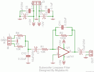
Simple Subwoofer Lowpass Filter using uA741 Single Op Amp Ic

This is the simplest Sub woofer Low Pass filter Circuit using uA741 single op amp ic. The circuit is very low cost with respect to their work. The cut off frequency of this circuit is 25Hz to 80Hz maximum. Using this circuit , you can easily design a 2.1 Sub-woofer Speaker System at your own Home. The circuit contains very few components.In Pakistan, the cost of this circuit with PCB is Rs:45 The same circuit is working in my own hand made sub-woofer system. So Try this [Link]

Lowpass Filter using uA741 Single Op-Amp Ic
Parts List: 

R1,R3,R4 = 10K 1/4W
R2=100K 1/4W
CY1,CY2 = 0.22uF Polyester
C1,C2 = 10uF/25V Electrolytic
IC1 = uA741A Single Op-Amp Ic + 8 Pin Ic Socket
3 Pin Male & Female Connector x 2
2 Pin Male & Female Connector x 1
PCB as in required size 4.5 cm x 3.4 cm
Read More..

Sunday, April 7, 2013

Skema Audio Power Amplifier with IC AN7106K

This Schematic must use the IC AN7106 because itsnt similarity, and some components. Minimum voltage is 1,8 Volt and Maximum voltage is 4,8 volt . It,s so very low voltage require. Recomended voltage is 3 volt , dont provide voltage too high it can make damage IC. Maximal Output 2 X 0,14 watt , this is stereo amplifier. And impedance is 32 Ohm.

See Schematic and package IC AN7106K below :


Package IC DIP24
Click Image to view enlarge.
 Good Luck !!

Read More..

Thursday, April 4, 2013

555 IC PWM Controller Circuit Grounded and Ungrounded Load


While keeping the oscillator frequency relatively stable, this 555 based PWM controller features almost 0% to 100% pulse width regulation using the 100k variable resistor. To give a frequency range from about 170Hz to 200Hz , the frequency is dependent on the 100k pot and 100n. This is the figure of the circuit;


You can see the charging and discharging of the 100n cap is done through output pin 3, and this provide a push-pull symmetric drive for easy pulse-width setting. You can see two versions, the left side for grounded load, and the right side for ungrounded load. The grounded one use pin 7 to drive the transistor, while the ungrounded one use the same push-pull output pin3, this difference is needed because wen need an inverted phase to provide consistent potentiometer scale on both version. [Circuit source: talkingelectronics.com]
Read More..