Monday, November 17, 2014
14W Class A Amplifier Circuit with 2N3055

Improving Performance Bass Guitar
2. Know your bass character of us, whether inclined treble, middle, or ngebass (low). From here our reference point. If soundnya not in accordance with our desires, try to correction with tone control / equalizer.
3. There are so many factors affecting the bass sounds, ranging from strings, pickups, body wood, neck & fingerboard.
Try to identify the character masing2, eg the influence of wood types, pickup types, etc..
From there we can determine which one should be modified.
Chain audio a bass sound as follows
Strings-> pickup-> Preamp / Tone Control-> Connection Cable-> Amplifier
Well, just select which one would aja in mod.
Actually the material (wood) body / neck / fingerboard also influence:
String-> Body/Neck/Fingerboard-> Pickup-> Preamp / Tone Control-> Connection Cable-> Amplifier (+ Speaker)
Only if you replace the body just wrote instead of bass.
So, if you can choose a distinguished bass wood is good, Ntar if you want to be upgraded more easily.
If wood is not good (Agathis), although the results are less than the maximum upgrade.
Sunday, November 16, 2014
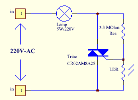
Triac Light Switch circuit
Saturday, November 15, 2014
Introduction to Cellular Communications 2
Increases in demand and the poor quality of existing service led mobile service providers to research ways to improve the quality of service and to support more users in their systems. Because the amount of frequency spectrum available for mobile cellular use was limited, efficient use of the required frequencies was needed for mobile cellular coverage. In modern cellular telephony, rural and urban regions are divided into areas according to specific provisioning guidelines. Deployment parameters, such as amount of cell-splitting and cell sizes, are determined by engineers experienced in cellular system architecture.
Provisioning for each region is planned according to an engineering plan that includes cells, clusters, frequency reuse, and handovers.
Cells
A cell is the basic geographic unit of a cellular system. The term cellular comes from the honeycomb shape of the areas into which a coverage region is divided. Cells are base stations transmitting over small geographic areas that are represented as hexagons. Each cell size varies depending on the landscape. Because of constraints imposed by natural terrain and man-made structures, the true shape of cells is not a perfect hexagon.Clusters
A cluster is a group of cells. No channels are reused within a cluster. Figure 4 illustrates a seven-cell cluster.| A cluster is a group of cells |
Frequency Reuse
| Frequency Reuse |
Cells with the same number have the same set of frequencies. Here, because the number of available frequencies is 7, the frequency reuse factor is 1/7. That is, each cell is using 1/7 of available cellular channels.
Cell Splitting
Unfortunately, economic considerations made the concept of creating full systems with many small areas impractical. To overcome this difficulty, system operators developed the idea of cell splitting. As a service area becomes full of users, this approach is used to split a single area into smaller ones. In this way, urban centers can be split into as many areas as necessary to provide acceptable service levels in heavy-traffic regions, while larger, less expensive cells can be used to cover remote rural regions.| Cell Splitting |
Handoff
The final obstacle in the development of the cellular network involved the problem created when a mobile subscriber traveled from one cell to another during a call. As adjacent areas do not use the same radio channels, a call must either be dropped or transferred from one radio channel to another when a user crosses the line between adjacent cells. Because dropping the call is unacceptable, the process of handoff was created. Handoff occurs when the mobile telephone network automatically transfers a call from radio channel to radio channel as a mobile crosses adjacent cells.| Cell Phone Handoff |
Friday, November 14, 2014
PHOTO SWITCH CIRCUIT USING NE 555
Circuit Diagram and Parts List

Important Points
- Assemble the circuit on a good quality PCB or common board.
- To setup the circuit switch on power supply, connect a multimeter across LDR and adjust R1 so that voltage across LDR is just below 1/3 supply voltage. Ensure that relay is off in this condition. If not reduce voltage across LDR further more by adjusting R1 to make relay off.
- Now cover the top of LDR using a black paper and see the relay gets activated. If not, make further adjustments with R1. Nothing to care after some trial and error you will get the correct set piont of R1 where the circuit works. This circuit is nothing great, but some simple basics. I have tested this and got good results.
- If there is some chattering in the relay, that may be because off the difference between the turning on and turning off voltages. This can be avoided by connecting a resistor whose value is equal to 1/2 the resistance of LDR at illuminated condition.
Thursday, November 13, 2014
NJM2582 bassed 4 channel video amplifier electronic project circuit with explanation
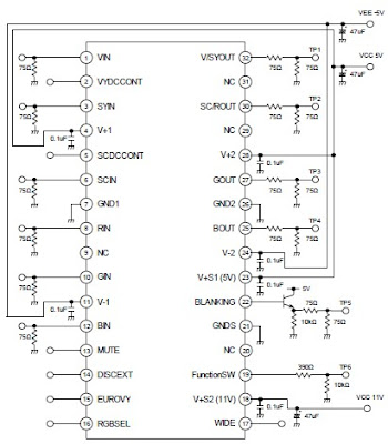
A very simple 4 channel video amplifier electronic circuit project can be designed using NJM2582 ic suitable for video applications with SCART connector . Design of the circuit is very simple and require few external electronic parts .
Some features of the NJM2582 are : Operating Voltage ±5V, +5V, +11V ; 6input 4output , 2input 1output Video SW , Internal LPF , 6dB Amplifier , Internal 75Ω Driver Circuit , DC output for SCART (FUNCTION SW, BLANKING) .
DC motor 12V speed controller circuit with explanation
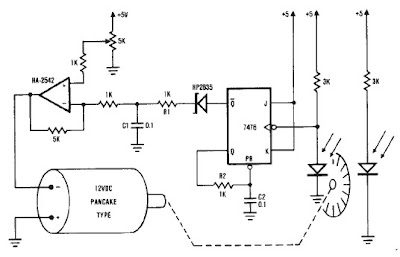
A very simple encoder circuit for a dc motor can be constructed using this circuit diagram . As you can see in the circuit diagram , the system shown consists of the HA-2542, a small 12-Vdc motor, and a position encoder. During operation, the encoder causes a series of constant-width" pulses to charge CI. The integrated pulses develop a reference voltage, which is proporţional to motor speed and is applied to the inverting input of HA-2542, The noninverting input is held at a constant voltage, which represents the desired motor speed. A difference between these two inputs will send a corrected drive signal to the motor, which completes the speed control system loop.
As you can see the circuit requires few external components , but because of the encoder wheel it has a limitations of use .If you put a pulley under the encoder wheel you can command the speed of other device , by connecting the (motor and other device ) using a belt